StudentShare
Contact Us
Sign In / Sign Up for FREE
Search
Go to advanced search...
Free

Design for the Attitude Control System - Essay Example

Cite this document
Summary
This essay "Design for the Attitude Control System" focuses on the control system toolbox that helps in modeling, analyzing, and designing the control system they develop a relationship between autopilot and flight dynamics. This relationship established gives a new approach to science…
Download full paper File format: .doc, available for editing
GRAB THE BEST PAPER94.2% of users find it useful
Design for the Attitude Control System
Read Text Preview

Extract of sample "Design for the Attitude Control System"

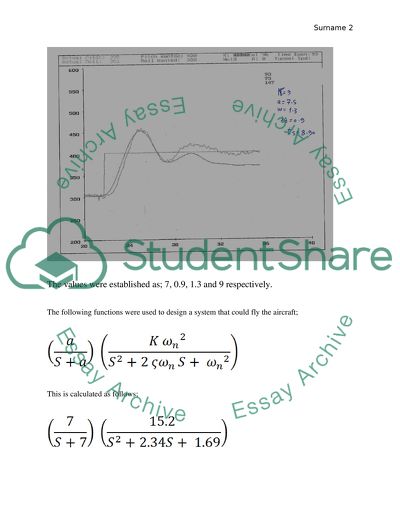
Attitude Control System Design for the Attitude Control System Procedure Stage The F-16 was run at different tunnel speed with different values for  to establish a perfect graph and values. The values were established as; 7, 0.9, 1.3 and 9 respectively. The following functions were used to design a system that could fly the aircraft; This is calculated as follows; Stage 2 Another transfer function was designed that is to be added to the system to ensure that the aircraft follows a particular profile. The value obtained was 10 that certified the function. This was followed by the transfer of the function to the added system; Thereafter, the system was tested at several tunnel speeds to ensure that the model followed the desired mission profile. During the process, the kh values were recorded at different tunnel speed. The kh values were recorded and a graph of kh against the tunnel speed was established. ts kh 6 0.19 6.3 0.14 7.3 0.12 8.5 0.11 From the graph equation, the value for kh can be established at any given speed with the linear equation. Discussion High accuracy is required for many aircrafts. Momentum-based attitude control system actuators developed for aero planes are used to meet these requirements. This paper discusses an auto pilot design model capable of measuring various flying parameters such as lift and drag. The main objective of the discussion is to study the development of a control system through the designed scheduled autopilot that enables the flying of a model at different speed conditions in the air. Aircraft have been designed by different parameters and analysis is needed to establish their effects on the performance of the vehicle. The Wright brothers used the wind tunnel to study the performance of various types of airfoils. There have been advanced wind tunnels that are used to determine the characteristics of full scale aircraft. On the other hand, use of the wind tunnel in determining flight characteristics and performance of full scale aircraft remains an expensive exercise and time consuming proposition. Due to advancement in information systems and technology, high speed computing helps determine flight performance of aircraft designs through the use of virtual tunnels. This process involves a computer generated model that is plugged in a Computational Fluid Dynamics (CFD) program that determines flow characteristics. The results obtained are compared to those found from the real wind tunnel test and the real aircraft performance in flight. However, several studies have been conducted to demonstrate validity and efficacy of the virtual wind tunnel. In this discussion, the two processes are introduced during undergraduate Aircraft Design class. Scale models of different types of aircraft such as the trainer, transport, fighter, and UAV are studied. The scaled models are installed in low speed cross-section wind tunnel used to establish the lift and drag coefficients and pressure profiles. Design of a virtual model of the corresponding aircraft by use of SolidWorks is also done. The virtual models developed are imported to the SolidWorks Flow Simulation software. The low speed virtual wind tunnel is simulated in Flow Simulation to establish lift and drag coefficients as pressure profiles are established for various aircraft at different angles of pitch, yaw, as well as roll. The results are then compared with the results obtained from real wind tunnel tests. The purpose of this experimental exercise is to help appreciate the importance of virtual testing. This helps ascertain the time and costs saved during the exercise. It also helps in understanding the reason for the closure of large wing tunnels in the U.S and reasons for discrepancies between the two methods used in designing of aircraft. Some of these discrepancies include the effect of differences in surface roughness, wing tip vortices, and viscosity among others. Part of this exercise involved generation of aircraft design generated from a laboratory report to be used in Aerodynamics laboratory. The purpose of the project was to ascertain a control system that aids the design of a scheduled auto pilot to enable a steady flying model at different speed conditions of air. The model at study is the F-16 aircraft. The PI elements are to be examined so that an attitude control system for the model is developed at a given mission profile and gain. The characteristics of the model under different speed conditions were understood so that a desired control system design is developed to counter the changes in wind speed. The errors that occurred in the project needed to be established by comparing analysis of the behaviour of the model to the teal system and the simulink simulated system (Lamar and Frink 639-645). The design process of an aircraft is an iterative process that includes prototyping and CFD analysis. In the early development stages of an aircraft, conceptual and preliminary design iterations look expensive and consume a lot of time. However, the Rapid Aircraft Design and prototyping Iteration Process makes the design process fast and reduces costs. The design students are capable of tweaking the design, perform sizing and performance analysis test, redraw sketches and update the CAD drawings and perform the CFD analysis to check for any improvements required. Once the iteration process is done, the design stage is simplified and performed faster with subsequent iteration. The prototype and or 3-D printing can be done for the scale models to be used in the wind tunnel analysis. As a result, design students learn the task needed to prepare the models for both wind tunnel and CFD analysis. An evaluation of how the CFD is developed into a conceptual design method is achieved by McCormick. CFD is also known to be an effective design tool when evaluation of aerodynamic performance for NASA Research Announcement (NRA) project is done (Lamar and Frink 639-645). As the designer goes through the iterative process, the importance of a good starting point is inevitable. The traditional aircraft design requires design of several aircraft that fit mission profiles. Sketches are drawn b hand using quick back of the envelop approach. After contemplation, calculations, tradeoffs, and discussions, the design process proceeds to use of CAD. During the CAD process, several limitations and constraints that cannot be realized during the manual calculations erupt. At the same time, additional features that the plane could have are also realized. Airfoils characteristics are studied so that the best that matches the mission objective is chosen. Upon completion of CAD design, the airfoil is prototyped with inexpensive materials or a 3-D print model. Airfoil prototyping are made of plywood and balsa wood and are covered with monocote film to attain a smooth surface finish. The 3D-printed models and the hand-made prototypes are then prepared for the wind tunnel testing. The purpose of the wing tunnel testing is to measure the drag and lift coefficients. The designers learn the limitations of the wing tunnel test during the experiment performed. This aids in internalizing the concepts of boundary layer, Reynolds number, scaling, tip vortices, free stream velocity, steady and unsteady air, the speed limitations, surface finish and errors from the equipment. It is also important to perform the CFD analysis of the designed CAD after doing the wind tunnel method. The CFD can be change the surface finish of the air foils which is used to establish the effects on lift drag CFD flow visualization. The project involved the study of an airplane model in an air tunnel through air simulation at desired speed and conditions. The model was equipped with all the necessary instruments needed to measure various air flying parameters such as lift and drag among others. The purpose of the study was to develop a control system through design work of a scheduled autopilot that ensures flying of the developed model at different speed conditions in the air. The designer also wanted to understand the behaviour of the model at different speed conditions that the desired control system should adapt to when there are changes in wind speed. The experiment also considered the errors that could occur as the experiment was being done. To ascertain this, study of different weather conditions on the aircraft and its performance were studied. Several instruments were used to create an artificial conditions desired so that necessary observations could be made. One of the tools used was the wind tunnel which on the other hand is not a perfect simulation of environmental conditions since the degree of flaw can be found by the a measured calculation referred to as the Reynolds’s number (Lamar and Frink 639-645). The Wind Tunnel Principle This simulation method generates uniform air flow with low turbulence intensity for thermal and hydraulic testing. The devices are used in various industries such as aerospace, automotive as well as defence and play an important role in electronics thermal management. The wind tunnels are available in different sizes and shape ranging from 30 cm long those that can accommodate a passenger plane. There are different types of wind tunnels. However, there are two types; open type that draws air from ambient and exits it back to the ambient and the closed loop wind tunnel. The closed loop wind tunnel has an internal air circulation that happens in a loop and separates the air from the outside ambient air. Temperatures in the closed loop wind tunnel are controlled by heaters and heat exchangers and are varied from over 100ºC. Conclusion Complete design of attitude control has four phases; specification of task to be performed by the system, for this case is an aircraft and selection of important components of the system, design of controller linking sensors to torques, verification of the design, and construction of the system. One approach of design of a controller is issued in the theory of optimal control. According to this theory, there are difficulties in applying it to the system in nonlinear and multidimensional cases for large-angle, and three axis attitude control systems. Computation of control laws for the system becomes time consuming and even when control laws are computed, they become difficult to implement. Such difficulties are responsible for limited enthusiasm when applied in the optimal control theory used for control laws in complex systems. However, this theory is important in analysis of performance of a system. Another approach frequently in practice is the pick a structure of the control law. This approach looks adequate on physical grounds with the test results analysed by computer simulation. The success of this approach depends on two factors; familiarity of the designer with the general properties of the system and validity of the inference made from the results of simulation. Simulation is concerned with accuracy and completeness of the system. Simulation is termed accurate if error between the simulated response and response for the actual system to a given control situation i.e. the initial condition and forcing function are small. It is also complete when the behaviour of the system for probable control situation is inferred from collection of cases simulated. Simulation is complete once all possibilities are accurately simulated. However, in most scenarios happening in practice, the number of possible control situations is larger than practical simulation. In such scenarios, it is important to justify inference made from the limited collection of test to the overall or global behaviour of the system. In the absence of this, the designer cannot ascertain all possible control situations from system failure included in the test sample. The ad hoc design procedure becomes realistic when followed by global analysis whereby the behaviour of the system is bound to the worst case. In such cases, control law easy to implement on physical grounds may be rejected if it leads to complex system that are unachievable with the available techniques of global analysis. ACS varies according to internal structures. For example torque may be generated form reaction wheels, control moment gyros or reaction jets. Attitude may also be measured by star trackers, sun or magnetic field sensors or inertial gyros. The designs are based on sound physical insight but often result to systems difficult to analyse. It is therefore important to approach the design problem from a general point of view by considering advantages of basic similarity of all attitude control systems. These are; their primary control objective of maintaining the aircraft to as close as desired attitude for successful flight and basic nonlinearity of three dimensional rotations. The study involved an analysis of naturally unstable aircraft design derived from theoretical pressure points on the longitudinal axis of the aircraft. An intentionally unstable design has great agility at subsonic speed. A reduction in drag leads to an overall increase in lift and enhanced STOL performance. Autopilots are mechanical and electrical systems designed to guide an aircraft without the assistance of human beings. The inertial guidance system fitted in the autopilot system accumulates errors over a period of time which may in turn corrupt positional data. The longer the flight, the more the errors accumulated. The errors can be corrected by a number of features such as autopilot loop, height control, and heading control autopilot. There are assumptions made during calculation of flight dynamics that includes the x and z axes in the symmetry plane. The origin of the axis system is taken to be the centre of gravity of the aircraft and the perturbations from equilibrium have small values as the aircraft body is assumed to be rigid with constant mass and quassi steady flow. The relationship that exists between autopilot system and flight dynamics is that the aircraft the system design analysis of the control system toolbox provides information to Simulink models and MATLAB tools used for flight simulation. Since the F-1 has two ways of controlling attitude; by single aileron and full rotation tail plane, the wind tunnel test was the best for it. The autopilot loop controls the aircraft’s flight path as it generates commends to the inner flight control loop. The commands are attitude commands that operate the aircraft’s control surfaces through the closed loop control system. This enables the aircraft to rotate at pitch and roll axes until the pitch and bank angles are equal to the commanded angles. The changes reflected in the aircraft’s pitch and bank angles cause the aircraft flight path to change through flight path kinematics. Height control is also an important factor in reducing errors in the autopilot system. The height is controlled by changing the pitch attitude of the model. The FBW (fly by wire) pitch rate controls the flight control system to assist the autopilot integration. The pitch attitude command loop responds faster than the height loop response by fractions of a second. The height error gain or gearing is chosen so that the frequency where the open-loop gain equated to 0 is below the bandwidth of the pitch attitude loop. This ensures a stable and well damped height loop so that a fast pitch attitude response is achieved. The control system toolbox helps in modelling, analyzing, and designing the control system they develop a relationship between an autopilot and flight dynamics. This relationship established gives a new approach to science and mathematical modelling of aircraft designing hence the traditional methods of various parameters of aircraft motion are examined in current computational tools and multi-variable modes. Stability is defined as the response of the model in study to the consternations in flight conditions from the dynamic equilibrium. The response of the system to control inputs is also looked at. Flight mechanics has been divided into two; the static stability and the dynamic stability. Static stability is the initial tendency of the aircraft. The airplane remains stable when its original equilibrium position is not interfered with. Dynamic stability is the initial tendency of the model when disturbed until it returns to its original equilibrium position whether the model returns to initial equilibrium or it followed a sequence of damping oscillation. Gain scheduling is a widely accepted approach for design. Non linear systems using a family of linear controllers provide satisfactory control for different operating point of the system to be controlled. Computer simulation programs used are used to calculate the real outputs. As the tunnel speed changes, it is observed that the step inputs from the real system do not match the simulated response for the speed indicated in the nonlinear system. Work Cited Lamar, J.E., and N.T. Frink, “Aerodynamic Features of Designed Strake-Wing Configurations,” Journal of Aircraft, Vol. 19, No. 8, August 1982, pp 639-646. Sears, W.R., “On Projectiles of Minimum Wave Drag, Quarterly of Applied Mathematics, Vol. 4, No. 4, Jan 1947. Read More
Cite this document
  • APA
  • MLA
  • CHICAGO
(“Engineering Essay Example | Topics and Well Written Essays - 2500 words”, n.d.)
Engineering Essay Example | Topics and Well Written Essays - 2500 words. Retrieved from https://studentshare.org/engineering-and-construction/1641195-engineering
(Engineering Essay Example | Topics and Well Written Essays - 2500 Words)
Engineering Essay Example | Topics and Well Written Essays - 2500 Words. https://studentshare.org/engineering-and-construction/1641195-engineering.
“Engineering Essay Example | Topics and Well Written Essays - 2500 Words”, n.d. https://studentshare.org/engineering-and-construction/1641195-engineering.
  • Cited: 0 times

CHECK THESE SAMPLES OF Design for the Attitude Control System

The relationship between creative written and verbal expression and attitudes toward violence

Neuman identified seven parts to a classical or true experimental design: n; treatment or the independent variable, the dependent variable, pretest, post-test, experimental group, control group, and random assignment.... Post-treatment measures or the dependent variable that is considered in the research is the attitudes toward violence, and this will be collected and compared in order or determine whether there were significant differences in the attitudes changes of control and sample groups....
10 Pages (2500 words) Dissertation

Attitude of Young People on Dieting and Weight

"Attitude of Young People on Dieting and Weight" paper identifies the attitudes of young women on weight and diet, how these attitudes affect the development of obesity and identify the attitude of young men toward weight and height, and how these attitudes affect the development of obesity.... All we can hope is that the attitude that young people have towards dieting and weight can be transformed into their lifestyles so that incidences of young overweight and obese individuals are reduced....
7 Pages (1750 words) Essay

Human Factors in Cockpit Design

The system is capable of alerting and informing all potential problems visually and by voice to the pilot.... The paper "Human Factors in Cockpit design" discusses that aircraft and the most important part of its cockpit have gone through enormous changes and the human factor has been one of the most intangible determinants in designing the cockpit and always offers never-ending scope.... Cockpit design will also be impacted by the other technologies too and may culminate into totally a different shape and style not imagined by anybody so far....
10 Pages (2500 words) Term Paper

Advanced Systems Design Project

The device will have a paralyzed robot that will be in a position to reach a certain point via a lee way that can be determined before the implementation of the system.... To carry out the task the operators will be in a position to carry out the perception of the system that will be used in determining the error of the paper.... For the device to be pushed in a certain section, the operator will control the rewuest of the machine by emiting the signals from various sections....
13 Pages (3250 words) Essay

Childrens Attitudes in Using the GPS

The author of the present research paper "Children's Attitudes in Using the GPS" highlights that understanding the children's attitudes would be crucial in teaching the GPS and geographic information system or GIS into the educational curriculum of children in the United Kingdom, including Northern Ireland.... The more popular definition of attitude is that by G.... Allport in 1935 that defines attitude as 'mental and neural state of readiness organized through experience' (Eiser et al....
15 Pages (3750 words) Research Paper

Attitude Of Young People On Dieting And Weight

Therefore, overweight and obese individuals have a weight that is considered unhealthy since it predisposes them to conditions like diabetes, ischaemic strokes, hypertension and many conditions of the cardiovascular system (Andersen, 2008).... According to figures released by the Centers for Disease control and Prevention (CDC), obesity cases in the US have been rising from the past, and currently, the prevalence of obesity among adults in the US is 35.... This paper "attitude Of Young People On Dieting And Weight" discusses the study that shows that youths understand the importance of avoiding fast food....
6 Pages (1500 words) Research Proposal

Features of the Microprocessor Technology and its Introduction to Autopilot Systems

Autopilot systems are generally some form of an electrical, mechanical, or hydraulic system that could control a vehicle without human intervention.... Although autopilots are control systems widely used in various industries, autopilots are more identified with ships and aircraft's automatic navigation.... However, in the advent of the microprocessor technology, autopilot soon became a sophisticated piece of equipment capable of holding altitude, maintains heading, change of speed, attitude cruise, climb, descend, turn, and the usual pitch adjustment....
12 Pages (3000 words) Term Paper

Flight Simulator Training and Flight Test

For the flight simulator test to meet the required and the necessary objectives, they must consider both the abnormal and normal system operation cases (Allerton, 2009).... The laboratory experimentation was mainly concerned with the portion of lateral direction for the controlled system.... This is an aspect of flight simulation that is mostly applicable in the configuration of flight control systems that are more advanced.... During the performance of the performance of the flight simulation test experiments, the participants took part in the design and implementation of control systems that are longitudinal in nature and functionality....
9 Pages (2250 words) Assignment
sponsored ads
We use cookies to create the best experience for you. Keep on browsing if you are OK with that, or find out how to manage cookies.
Contact Us