StudentShare
Contact Us
Sign In / Sign Up for FREE
Search
Go to advanced search...
Free

Sheet Pile Design - Coursework Example

Cite this document
Summary
Sheet Pile Design.
Chang-Yu (2006, pp 126-127) stated; “when the shear stress at a point in soil exceeds or equals the shear strength of soil at the point, the point is in the failure state”…
Download full paper File format: .doc, available for editing
GRAB THE BEST PAPER92.6% of users find it useful
Sheet Pile Design
Read Text Preview

Extract of sample "Sheet Pile Design"

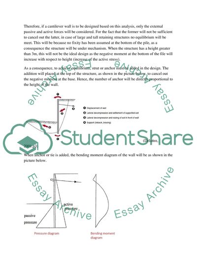
?Chang-Yu (2006, pp 126-127) d; “when the shear stress at a point in soil exceeds or equals the shear strength of soil at the point, the point is in the failure state”. In the situation where many failure points connect together into continuities, a failure surface is formed leading to a collapse of the excavation. This is known as overall shear failure. It should be noted that there are two main modes of failure for excavation where the push-in failure can be listed. The latter is caused by earth pressures reaching the limiting state on both side of a considered retaining structure, which thereafter moves towards the excavated area until the full-zone failure is reached. As movement can occur on the bottom part of the wall, the analysis of the structure will be taken as a free body. Thus there will be modified free earth support method (The free earth support revised method) and fixed earth support method. It is worth mentioning that both methods have assumed that active stress condition have been fully developed behind the retaining wall while the passive stress is right in front of the structure. This will allow for calculation using coulomb or Boussinesq theories that consider the actual stress distribution. 1. Modified free earth support method of analysis According to Clayton et al (1993, pp213-214), this method often gives the most economical design for retaining walls. For structure such as cantilever wall, the soil at the lower part of the pile should be strong enough to resist overturning moments. As shown in the above figure, the passive zone should be adequate in order to prevent lateral deflection and rotation at the lower end of the wall. However, the main principle behind the modified free earth support method of analysis is the assumption that the embedment of the wall is allowed to move and this will be to a certain distance under the action of the applied lateral earth pressure; this will cause the occurrence of negative bending moments at the considered location. This results in a statically determinate structure, only stable under certain conditions. Therefore, if a cantilever wall is to be designed based on this analysis, only the external passive and active forces will be considered. For the fact that the former will not be sufficient to cancel out the latter, in case of large and tall retaining structures no equilibrium will be meet. This will be because no fixity has been assumed at the bottom of the pile, as a consequence the structure will be under mechanism. When the structure has a height greater than 3m, this will not be the ideal design as the negative moment at the bottom of the file will increase with respect to height (increase of the active stress). As a consequence, to achieve equilibrium, strut or anchor must be added in the design. The addition will placed at the top of the structure, as shown in the picture below, to cancel out the negative moment at the base. Hence, the number of anchor will be directly proportional to the height of the wall. (Delattre, 2001,p3) When anchor or tie is added, the bending moment diagram of the wall will be as shown in the picture below. It can be seen that when moment is created by the anchorage at the top, at the bottom of the pile, the negative moment has been cancelled out; this will be only if both are equal or the former is greater than the overturning moment. As a consequence equilibrium has been satisfied; a moment created by the tie is balanced by the active earth pressure above it. Lancellotta (1995, pp305) explained: “the failure mechanism envisaged in this case involves a rotation about the anchor”. Here, the rotation of moment at C (shown in the above picture) will enable for calculating the depth by which the pile has to be embedded to satisfy equilibrium against rotation; in other words, the shear strength of the soil is mobilised with respect to the depth of embedment. The equilibrium of horizontal translation gives then the force of the anchor as a high anchorage force will result in movement of the pile towards the retained soil. In conclusion, the analysis of the wall has considered the limit state of the soil retained causing both rotation and translation of the wall as well as vertical equilibrium (in the case where inclined tie has been used). Nevertheless, it is worth mentioning that to satisfy and complete the analysis, the sum of vertical forces should be equal to zero. This is the vertical forces on the wall should not exceed the frictional resistance that exist between the retaining structure and the soil. Azizi (2000, pp 609-610) stated: “with the increasing height, a series of anchors, as oppose to single anchor, might be necessary, so as the deflection and control the bending moment”. The bending moment of the above case is shown in the picture below: (Azizi,2000, pp 609). The procedure explained below is used to produce the pressure diagram, important in determining the depth of the embedment, the anchorage force and the maximum bending moment in the pile, with the assumption that the active pressure is mobilised. Both active and passive effective thrusts distribution along both sides of the pile are calculated using a factor of safety on the coefficient of passive earth pressure. Azizi (2000, pp 611-612) stated: “ it is a usual practice to reduce the actual coefficient of passive pressure by a factor of safety equal to 2”. Afterwards, the net pressure diagram is found by addition of the total active and passive thrusts on both sides of the considered pile. To satisfy the moment equilibrium, rotation should be allowed at the anchorage point, giving an equation with one unknown which is the embedded depth required. In the other hand, the anchor force will be calculated from the horizontal force equilibrium equation, allowing the shear force diagram along the pile to be drawn. It is worth mentioning that the location of zero shear force is the same as the location of the maximum bending moment applied on the retaining structure. Azizi (2000, p630) commented: “this procedure usually overestimates both the maximum bending moment and the anchorage force”. From experience and previous designs, it has been confirmed that the conservative approach of the modified free earth support method of anchored pile analysis has led to overdesigning therefore uneconomical structures. This is because pressure redistribution takes place around the pile right after the yielding occurred. The redistribution allows calculating the value of the moment at failure as the elastic moment is by far greater than the plastic moment. To allow for this, moment redistribution factors are used. By lowering the maximum moment of the sheet pile, the design will be underestimated, leading to a more economical approach. Nevertheless, the field conditions should also be considered. Due to flexibility a pile embedded in clay, the analysis should disregard the reduction factor as suggested by skempton (Azizi, 2000, p632). When the reduction is done in the sand, only a portion of the passive pressure will be mobilised. As a consequence, displacement at the toe of the pile will be noticed with respect to the anchorage point causing stress redistribution behind the wall. The movement will therefore be the main factor affecting the reduction of the value of the maximum bending moment. The following expressions are used in order to calculate the corrected bending moment used to select an appropriate sheet pile section (Mc): For sheet piles driven in sand: Mc = Mm – 0.5*(Mm –Mr) For sheet piles in medium and dense silty sand Mc = Mm – 0.25 * (Mm – Mr) Where Mm: maximum bending moment determined from the net pressure diagram Mr: reduced bending moment obtained from Rowe’s method This method is to limit the reduction on the calculated moment after pressure diagram and allow for adequate selection of steel section; keeping in mind that a large reduction will result in a thinner section that might cause problem considering the construction method (technique for driving the pile in the soil to the required depth). 2. Fixed earth support method Chang-Yu (2006, pp 128-129) stated: “the fixed earth support method is to assume that the embedment of the retaining wall seems to be fixed at a point below the excavation surface.” This is illustrated in the figure below where a cantilever wall with anchor is used. For a fixed point to be assumed, contrarily to the previous free method, the pile has to be considered as flexible but has to be driven to sufficient depth. At a certain depth d below the ground level, the passive stress will be increased in such a way that no rotation at the pile toe will occur. The bottom of the retaining structure will be considered as rigid in this case; this is considered as principle of the fixed earth support method. Therefore, to make a comparison with the free earth support method, in this method, the embedded part of the pile will be much longer. Clayton (1993, pp 226-227) explained: “ in this method, the stresses on the wall immediately above the toe are replaced by a single force some distance up the wall and the sheet piling is considered to be held vertically at this point”. In other words, the embedded part of the retaining structure is allowed to rotate about a fixed point O, as shown in the about figure. As explained previously at a certain height, where the value of the active pressure is much bigger than the passive resistance, free earth support method is not the ideal method for cantilever pile. To achieve equilibrium, anchorage was necessary (or strutted piles). However, the fixed earth support method will be very much recommended for cantilever pile due to the fact that passive resistance becomes higher with increased length of the embedded part of the pile. The fixity of the method will be enough to satisfy equilibrium and make the construction more economical as compared to strutted piles (the strut load will not be required). Nevertheless, it should be borne in mind that the use of anchor will still be important to maintain horizontal stability and allow for the bending moment diagram to come back to zero at the top of the pile; keeping in mind that the active pressure will still be greater than the passive resistance. The nature of the support will make the structure statically indeterminate, giving necessity to consider the deflections. As a result, the maximum bending moment of the pile will be much lower than the free earth support method. The benefit of the free earth support method is that the structure is statically determinate; in other words equilibrium will be met by satisfying the three static equations: vertical, horizontal and moment equations. The difficulty caused by the fixed earth support method is the calculation of statically indeterminate structures even for simple soil profiles. The Azizi (2000, pp 636) recommended the Blum equivalent beam method for analysis of the fixed earth support. However, it is worth mentioning that the suitability of this procedure will depend on how realistic assumptions made by the method are in relation with the actual soil condition of the site where the pile will be driven. The design methodology is to divide the retaining structure into two hinged beam and analyse them separately as simply supported beam. The division is to be made exactly at the point of contraflexure, where the bending moment is zero. The main point with Blum’s method is the assumption that the point of zero net pressure (e) and the point of zero moment (g) occur at exactly the same depth as shown in the picture below. The fact that e and g have the same value will only be correct when the soil is completely homogenous; here only one layer of soil. Here, c is the position from where moment will be taken as explained previously and slope is assumed to be vertical and h is the height from the dredge level to the top of the pile. D’ is the depth of embedment where the passive resistance of the soil is fully mobilised in from of the wall. This value is far smaller than the actual depth D to which the pile has to be driven. Due to the fact that at depth D, there will be some active pressure in front of the pile and passive pressure behind the retaining structure. Azizi (2000, pp 636) explained that the above assumption (g=e) can only be justified if the ratio e/h is well between the value of 0.1 and 0.2. He added: “the error generated by assuming that e=g for ratios e/h0.2 is on the safe side since the maximum bending moment will be, in this case, underestimate”. As a conclusion, Blum’s method will be restricted on analysis of piles driven in homogenous soils and most importantly when e/h is between 0.1 and 0.2> in addition, it can be seen that this method is laborious and analysis has to be by computer. The depth D’ is determined after establishing the equation of the horizontal forces and equilibrium of moment with respect to the anchorage point in the upper half; keeping in mind that the pile has been divided into two statically determinate sections at the location of zero moment. With the two equation of the upper part determined, horizontal force of the anchorage and at the lower part of the considered part can be solved by equation of static. Regarding the lower part, an equation can be written by taking moment about C, the point where the pile is allowed to rotate. The actual required depth of the pile (D) will be e+1.2(D’-e) where e is the point of zero net pressure. Clayton (1993) advised to increase the value of the anchorage force by at least 15% to take into account the moment redistribution; this will be to design at failure. Nevertheless, as it has been assumed that the fixed earth support method has a rigid base, the value of the maximum bending moment will be much smaller. As a consequence, smaller section will be chosen for pile. One should state that the construction method should be kept in mind; drive a pile with a thinner cross-section to the required depth (considered to be high to achieve adequate fixity) will be delicate. In conclusion, for most case, the selected section will be bigger than the designed section as driving will become the deciding factor. BIBLIOGRAPHY Azizi,F.,2000.applied analysis in Geotechnics [e-book] London: Taylor and francis Available at: http://books.google.co.uk/books?id=_MzWBetcVhAC&dq=modified+free+earth+support+method&source=gbs_navlinks_s [accessed 17th July 2013] Chang-Yu, O.,2006. Deep excavation: theory and practice.[e-book] London: Taylor and Francis Available at: http://books.google.co.uk/books?id=lgfLrFUdk7EC&pg=PA127&lpg=PA127&dq=free+earth+support+method&source=bl&ots=GCGQSVXjXI&sig=ywiwVRFMJdil5Js1dJbURZIR6QE&hl=en&sa=X&ei=IRDjUdCvGY7u0gW6yoCwDw&sqi=2&ved=0CDgQ6AEwAg#v=onepage&q=free%20earth%20support%20method&f=false [accessed 17th July 2013] Civilwares.free.fr,2012. Sheet pile works and braced cuts. [pdf] New York:Marcel Bakker inc Available at: http://civilwares.free.fr/Geotechnical%20engineering%20-%20Principles%20and%20Practices%20of%20Soils%20Mechanics%20and%20Foundation%20Engineering/Chapter%2020.pdf [accessed 17th July 2013] Clayton,C., Milititsky,J. and Woods,R.,1993.earth pressure and earth-retaining wall.[e-book] London: Taylor and Francis Available at: http://books.google.co.uk/books?id=07YMiL7ZysYC&pg=PA213&lpg=PA213&dq=free+earth+support+method&source=bl&ots=i8xe1n5wP2&sig=YTNwu9-CE3cadMo0s_m5jNDz7_c&hl=en&sa=X&ei=nx7jUcWtJOeW0AXUm4H4AQ&ved=0CDsQ6AEwAw#v=onepage&q=free%20earth%20support%20method&f=false [accessed 17th July 2013] Honjo,Y.,Kusakabe,O. and Pokharel,G.,2002.foundations design code and soil investigation in view of international harmonisation and performance based design [e-book] London: Taylor and Francis Available at: http://books.google.co.uk/books?id=5hjGxxzhWjgC&dq=modified+free+earth+support+method&source=gbs_navlinks_s [Accessed 17th July 2013] Lancellota,R.,1995.geotechnical engineering.[e-book] London: Taylor and Francis Available at: http://books.google.co.uk/books?id=T9_LyV5W_NAC&dq=modified+free+earth+support+method&source=gbs_navlinks_s [accessed 17th July 2013] Ranjan,G. and Autor Rao,A.,2007.basic and applied soil mechanics [e-book] New Delhi: New age international Available at: http://books.google.co.uk/books?id=U2AvQrA6I4sC&printsec=frontcover&source=gbs_ge_summary_r&cad=0#v=onepage&q&f=false [accessed 17th July 2013] Read More
Cite this document
  • APA
  • MLA
  • CHICAGO
(“Sheet Pile Design Coursework Example | Topics and Well Written Essays - 2000 words”, n.d.)
Retrieved from https://studentshare.org/engineering-and-construction/1482587-sheet-pile-design
(Sheet Pile Design Coursework Example | Topics and Well Written Essays - 2000 Words)
https://studentshare.org/engineering-and-construction/1482587-sheet-pile-design.
“Sheet Pile Design Coursework Example | Topics and Well Written Essays - 2000 Words”, n.d. https://studentshare.org/engineering-and-construction/1482587-sheet-pile-design.
  • Cited: 0 times

CHECK THESE SAMPLES OF Sheet Pile Design

Structural Reliability of Hong Kong

Structural reliability is a probabilistic approach to quantify the potential success of a structure to provide the design needs throughout the intended service period.... Typically in structural design, reliability is factored into the random load and resistant factors.... Most structural design specifications are slowly transitioning into the Load/Resistance Factor Future plans are to develop the material into a structural reliability.... Through instruction of structural reliability concepts, an awareness of structural safety design and a better appreciation of expertise will be strengthened among future engineers....
43 Pages (10750 words) Essay

Shear Testing in Made Ground

Much development is taking place on old industrial brownfield sites due to the rise of urban regeneration schemes and the need to conserve green spaces in towns and city centres.... These presents challenges in liability, risk and costs.... Contaminated land specialists are expected… Comprehensive investigation of buildings, soil and water environment enables us to identify the potential hazards and develop a range of appropriate remediation solutions....
10 Pages (2500 words) Essay

Structural Design or Engineering

Structural engineers play a major role in designing and appraising the architect design.... Most of the complex structural systems are design using the basic structural Proper engineering design is required for all structural work as inferior designs have resulted to many catastrophic accidents such as the collapse of buildings, bridges underground tunnels, roofs and other structures.... It is therefore important to consider all aspects of a building especially in terms of applied loads so as to design a sufficient structure to resist these forces....
9 Pages (2250 words) Essay

Design Study/ Proposal for dissertation

Knowledge which can be established by this paper shall be used to determine the relationship between stress and atherosclerosis.... Applied research as… 33) helps to solve problems and helps control outcomes in real-life situations.... This research methodology will help meet the goals of this current study and identify the specific areas of concern for stress and atherosclerosis sufferers. The target lation for this paper shall cover patients 30 years and above who were admitted at the _____hospital from _______ to _______ with a diagnosis of atherosclerosis....
4 Pages (1000 words) Essay

Characteristics of Structureal Engeneering

The report includes an introduction to the brownfield sites and a detailed mechanism of remediation of a brownfield site.... An appropriate system of the foundation for the required building is selected with the retaining wall and ground floor system.... hellip; The remediation process is usually very expensive and cost-benefit analysis has to be done before arriving at a final conclusion that whether it is useful to redevelop it or not....
14 Pages (3500 words) Case Study

Structural Concept

In the analysis, BRIC-volume components containing non-linear material law GRAN sheet pile Wall for Embankment Stabilization Introduction It is possible to model piles in different ways using the SOFiSTiK modules.... ?design and construction of small earth dams.... A case in point is the combined pile-slab foundations.... Ground Slab/HASE/ASE, which is the flexible half space non-linear piles fall… It is also acceptable to consider the pile starting point also referred to as boss as an example and that is what this discourse deals with in the analysis....
2 Pages (500 words) Essay

Analysis of Sheet Pile Wall for Embankment Stabilization

"Analysis of sheet pile Wall for Embankment Stabilization" paper undertakes an analysis of sheet pile wall for embankment stabilization using and an assessment-modeling alternative of the piles.... A case in point is the combined pile-slab foundations.... It is also acceptable to consider the pile starting point also referred to as boss as an example and that is what this discourse deals with within the analysis....
7 Pages (1750 words) Coursework

Manufacturing Processes and Techniques

i) sheet metal/Press Brake: Mount of air motorMaterials used for the manufacture of sheet metalIn the manufacture of sheet metals, manufacturers roll large quantities of the available materials into sheets having differing thickness and then proceed to coat them with protective materials.... A thin oxide layer is used to prevent the rusting of the sheet.... Galvanized are readily available since they are the least expensive among sheet metals....
13 Pages (3250 words) Assignment
sponsored ads
We use cookies to create the best experience for you. Keep on browsing if you are OK with that, or find out how to manage cookies.
Contact Us