StudentShare
Contact Us
Sign In / Sign Up for FREE
Search
Go to advanced search...
Free

Dynamic and Control Subject - Assignment Example

Cite this document
Summary
This assignment "Dynamic and Control Subject" shows that coming to the explanation in common words, concerning Figure 1, we want the output Y of a process to be equal to or as close to the setpoint R as possible. Since the real systems are not ideal…
Download full paper File format: .doc, available for editing
GRAB THE BEST PAPER93.4% of users find it useful
Dynamic and Control Subject
Read Text Preview

Extract of sample "Dynamic and Control Subject"

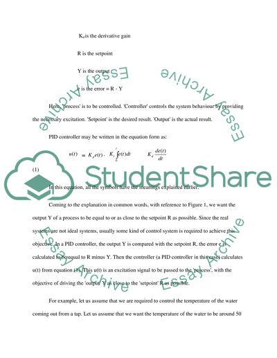
The principle of operation of a Proportional – Integral - Derivative (PID) controller is explained in detail in References 10]. Reference [11]is a source on programmable logic controllers which may be used in PID implementations. Reference [12] may be consulted as the source for the mathematical knowledge that is required to understand and design control systems. Schematic of a PID control system is shown in Figure 1. Figure 1. PID Controller In the figure, t is the time Kp is the proportional gain Ki is the integral gain Kd is the derivative gain R is the setpoint Y is the output e is the error = R - Y Here, 'process' is to be controlled. 'Controller' controls the system behaviour by providing the necessary excitation. 'Setpoint' is the desired result. 'Output' is the actual result. PID controller may be written in the equation form as: = + + (1) In this equation, all the symbols have the meanings explained earlier. Coming to the explanation in common words, with reference to Figure 1, we want the output Y of a process to be equal to or as close to the setpoint R as possible. Since the real systems are not ideal systems, usually some kind of control system is required to achieve this objective. In a PID controller, the output Y is compared with the setpoint R, the error e is calculated to be equal to R minus Y. Then the controller (a PID controller in this case) calculates u(t) from equation (1). This u(t) is an excitation signal to be passed to the 'process', with the objective of driving the 'output' Y as close to the 'setpoint' R as possible. For example, let us assume that we are required to control the temperature of the water coming out from a tap. Let us assume that we want the temperature of the water to be around 50 degree centigrade always. But let us assume that water is supplied to this tap by two separate water feeds. Let us assume that one of the water feed is always at around 30?C (cold water feed). Also, let us assume that the other water feed is always at around 70?C (hot water feed). We can see that to get the water from the tap at 50?C, we need to mix around 50% water from the hot water feed with the remaining 50% water from the cold water feed. This can be achieved by making the valve corresponding to the hot water feed 50% open (i.e., 50% closed) and at the same time, making the valve corresponding to the cold water feed 50% open (i.e., 50% closed). But, in a real system like this, one comes across several uncertainties like the temperature losses during the flow in the pipes due to radiation etc., which cannot be determined for certain since in this case, the radiation depends on the atmospheric temperature (or room temperature) also. Hence, when the valve corresponding to the hot water feed is 50% open and at the same time when the valve corresponding to the cold water feed is 50% open, the temperature of the water coming out from the tap may not be exactly equal to 50%. Let us assume that this temperature is 45?C. Now, in this problem, the setpoint R is 50?C while the output Y is 45?C. Now, according to Figure 1, R-Y= 5 ?C is calculated. This is the error e which is an input to the controller. Then the controller calculates 'u(t)' from Equation (1), this u(t) is in fact a signal which controls the valves. In this case, u(t) would instruct the valve corresponding to the hot water feed to open more than 50% (exact percentage would be known from u(t)). Opening the valve corresponding to the hot water feed x% would automatically mean opening the valve corresponding to the cold water feed (100-x)%. This ensures that the flow from the hot water feed is more than the flow from the cold water feed, which in turn forces the temperature of the water coming from the tap to go to 50?C. This way, the controller strives to make the temperature of the water coming out from the tap to be 50?C, and for a proper selection of the values for Kp, Ki and Kd, the controller usually performs its task satisfactorily. If the temperature of the tap water goes to 55?C for example, the error would be e=-5 ?C, and the PID controller would again calculate u(t) for this case. But the result this time would be to instruct the valve corresponding to the hot water feed to open less than 50% (hence to instruct the valve corresponding to the cold water feed to open more than 50%), so that the temperature of the water coming out from the tap reaches 50?C. The example presented in the previous paragraph (i.e., a mixer system) would be referred to throughout this assignment, and a PID controller design that is required for the question number 2 of the present assignment would be based on the problem (or the example) presented in the previous paragraph. Some of the terms that are commonly encountered while dealing with PID controllers would be explained now. a) Manipulated Variable The variable which can be directly manipulated or adjusted so as to enable the output to reach the desired value is called a manipulated variable. The weighted sum u(t) of proportional, integral and derivative actions is the value for this manipulated variable. In the mixer system example considered earlier, the percentage of opening (or closing) of the hot (or cold) water feed valve is a manipulated variable, since the temperature of the water coming out of the tap can be directly controlled using these valves. b) Process Variable The output (Y) of the Figure 1 is a process variable. In our example, the temperature of the water coming out of the tap is the process variable. This is in fact the output of the process. Purpose of a control system is to make the process variable as close to the desired value as possible, as quickly as possible, without oscillations about the desired value while reaching the desired value. c) Setpoint Setpoint is the desired value of the process variable. In our example, the desired tap water temperature (50?C) is the setpoint. d) Gain For a given setpoint, the proportional gain (Kp), integral gain (Ki), and derivative gains (Kd) are the three constants such that the value of the manipulated variable equals the proportional gain times the error plus the integral gain times the integral of the error plus the derivative gain times the derivative of the error. This can be seen from Equation (1). For a given setpoint, these are constants. e) Open Loop Control The schematic of an open loop control is shown in Figure 2. Figure 2 Open Loop Control Open loop control system is a type of control system where the process variable does not depend on error. In fact, the process variable is not compared with the setpoint, hence there is no question of calculating the error. This type of control is not useful when there are lot of uncertainties and when the process variable has to be tightly controlled. Open-loop control may be useful for well-defined systems. Here, relationship between input and the output can be accurately modeled. For example, determining the voltage to an electric motor that drives a constant load and runs at a constant speed is a good example of open-loop control. On the other hand, if the load varies, the motor's speed varies as a function of both the load and the voltage. In this case, an open-loop controller is insufficient. PID controller is not an open loop controller. f) Closed Loop Control PID control is a closed loop control and hence Figure 1 which is a schematic of the PID controller can tell about the Closed Loop Control also. In closed loop control, process variable is always compared with the setpoint to determine whether there is any error. A sensor system is needed to measure the process variable. If there is no error always, then there is no need of the closed loop control and open loop control is sufficient in this case. Closed loop control is expensive and complicated when compared to open loop control. If there is an error, and if it is inevitable to control the error, a closed loop control is absolutely required. A PID controller is quite general and may virtually be used to control anything that is measurable. Most of the times, one can always arrive at the optimal (or good) values for Kp, Ki and Kd, so that the controller makes the process variable reach the value that is equal to the setpoint quickly and elegantly. There are different algorithms (e.g., Ziegler–Nichols, Cohen-Coon) for obtaining these gains. Algorithms may be implemented using well known packages like MATLAB. Also, there exist software which can get the optimum values for these constants. Even when the setpoint is varied, one can calculate the new values for the gains Kp, Ki and Kd. The mixer system (our example problem) requires a closed loop control system. Closed loop control systems (including PID systems) may be realized using programmable logic controllers (PLC), digital processors, electronic circuits, embedded systems etc. For complicated applications, even a digital computer may be employed. g) Overshoot Overshoot refers to an output exceeding its final, steady-state value. Overshoot is associated with oscillations. When the manipulated variable pushes the process variable towards the set point, sometimes, before achieving the value that is equal to the setpoint value, the manipulated variable may achieve a value that is beyond the setpoint value. Next, there would be oscillations about the setpoint value before the steady state is reached and (ideally) the manipulated variable takes the setpoint value. Hence the overshoot may be defined as the maximum peak value of the response curve measured from the desired response of the system. 2) The mixer system problem is explained in the above answer (Answer 1). The problem is to design a PID controller so as to maintain the tap water temperature at 50?C. Question 2 implies that the tap water temperature should be somewhere between 30?C to 70?C. Here, setpoint is set as 50?C. It is assumed that the hot water feed always supplies water at 70?C, and the cold water feed supplies water at 70?C, always. It is also assumed that controlling one valve automatically controls the other valve such that the tap can always flows full, e.g., keeping the valve corresponding to the hot water feed 60% open will automatically make the valve corresponding to the cold water feed 40% open. Also, we will actively control the valve corresponding to the hot water feed only; the other valve would passively adjust itself. Also, it is assumed that one does not need any time for mixing. This implies that keeping the valve corresponding to the hot water feed 50% open (which in turn implies keeping the valve corresponding to the cold water feed also 50% open) results in a tap water temperature of ((30+70)/2) ?C immediately. Also, the mixing volumes should be large. The normal (or the natural) position of the valves is 50% open. Hence the problem is to determine Kp, Ki and Kd for the setpoint that is set to 50?C. While 'tuning', i.e., while obtaining a good combination of Kp, Ki and Kd , goal is to minimize rise time, overshoot and steady state error. Overshoot has already been explained earlier. Steady state error is the error which cannot be avoided, and the rise time is the time needed to achieve the steady state. Clearly, steady state error should almost be zero (if not equal to zero), and rise time and overshoot should be as small as possible. Now the problem is to find the combination of Kp, Ki and Kd which provides these desired characteristics. Also, we need to find out the rise time, overshoot and steady state error characteristics expected from the system. We need to have a temperature sensor to measure the temperature of the tap water (process variable). The sensor output has to be compared against the setpoint. The error is calculated. Then, based on this error, the PID controller calculates how much percentage of the valve that corresponds to hot water feed should be open (i.e., the PID controller calculates the manipulated variable). The controller can be tuned by trial and error. But this needs too much of trial and error and hence this method has not been used here. A method known as the Ziegler-Nichols closed loop tuning method (or simply Ziegler-Nichols method) is relevant to the present problem. In this method, one should remove the integral and the derivative action. One should set the integral time (Ti) to 999 or its largest value and set the derivative controller (Td) to zero. Next, one should create a small disturbance in the loop by changing the set point. Next, adjust the proportional gain until the oscillations have constant amplitude. Then, one should record this proportional gain value (denoted now as Ku) and period of oscillation (denoted now as Pu). Now, Kp, Ti and Td are given by: Kp = Ku/1.7, Ti = Pu/2, Td = Pu/8. One can note that Ti = Kp/Ki and Td = Kd /Kp . A method known as the Process Reaction Curve is also widely used. It is also known as the Ziegler-Nichols open loop tuning method. Although it is an 'open loop' tuning method, the method has been used to tune PID controllers which are essentially closed loop controllers. In the Process Reaction Curve method, a step input is given to the system. Output is monitored until it reaches the steady state. The output versus time curve is called the process curve for the system. From this curve, one can get the rise time, steady state error etc. One has to find a point on this curve such that the tangent to the curve at this point has the maximum slope when compared to tangents drawn to the curve at any other point on the curve. Once we get this point and draw a tangent to the curve at this point, together with the Process Reaction Curve, we can obtain the tuned values of Kp, Ki and Kd , using the definitive equations. This method has been used here because of its simplicity. It is a standard practice to use the method for tuning a PID controller although any PID controller is essentially a closed loop controller. The transfer function for a PID controller is given by: (2) One can get the Process Reaction Curve from the MATLAB command 'step', and by using the transfer function for the whole system. The curve is somewhat similar to Figure 3. Figure 3 Closed Loop Step Curve From the curve, one can see that there is no steady state error and there is no overshoot. Rise time is about 0.9 second and since it is quick, it is acceptable. References [1] Bernard Friedland, Advanced Control System Design, Englewood Cliffs, 1996 [2] Ching-Fang Lin, Advanced Control System Design, Englewood Cliffs, 1994 [3] Stanley M Shinners, Advanced Modern Control System: Theory and Design, Wiley New York, 1998 [4] M Thoma, M Morari, Advanced Topics in Control System Theory, Springer, London, 2005 [5] G.J. Thaler, R.G. Brown, Analysis and Design of Feedback Control System, McGraw-Hill, 1960 [6] W K Gawronski, Structural Dynamics, Springer, 2004 [7] Benjamin C. Kuo., Automatic Control System, PHI, 1988 [8] D. P. Sante., Automatic Control System Technology, Prentice Hall, 1980 [9] Savant., Basic Feedback Control System Design, McGraw Hill, 1958 [10] George Ellis., Control System Design Guide, Academic, San Diego, 1991 [11] W Bolton, Programmable logic controllers, Newnes, 2009 [12] J O Bird, Higher Engineering Mathematics, Butterworth-Heinemann, 1996 Read More
Cite this document
  • APA
  • MLA
  • CHICAGO
(“Dynamic and control subjest Assignment Example | Topics and Well Written Essays - 2500 words”, n.d.)
Retrieved from https://studentshare.org/family-consumer-science/1416700-dynamic-and-control-subjest
(Dynamic and Control Subjest Assignment Example | Topics and Well Written Essays - 2500 Words)
https://studentshare.org/family-consumer-science/1416700-dynamic-and-control-subjest.
“Dynamic and Control Subjest Assignment Example | Topics and Well Written Essays - 2500 Words”, n.d. https://studentshare.org/family-consumer-science/1416700-dynamic-and-control-subjest.
  • Cited: 0 times

CHECK THESE SAMPLES OF Dynamic and Control Subject

Sex of Group-mates as Determinant of Sex Differences in Group Conformity

In this study, the researcher will examine the conformity level of men and women when placed in a group with the opposite sex.... His hypothesis is that women are more prone to conform when placed in a group with mostly men rather than a neutral group.... hellip; Research has established that the presence of social information may also influence conformance, as individuals who are aware that others have donated a certain amount to charity are more likely to donate an equal or greater amount....
17 Pages (4250 words) Thesis

Hybrid System

HYBRID SYSTEM By Lecturer: Institution of Affiliation: City and State: Date: Abstract The report provided a brief introduction and in this part, the author attempted to introduce the subject matter.... Hybrid systems are also used to model varied system such as physical systems, logic dynamic controller and also Internet congestion....
4 Pages (1000 words) Assignment

Exploring the Logic of Experimental Design

Experiments involve observation of phenomena that is made to occur in strictly controlled environments and situations where one or more variables are dynamic and others are static.... The design of an experiment determines the feasibility of the intended results to the subject of the experiment, which makes experimental design a crucial factor in all analytical work (Scott, 2010).... An experiment is an inquiry into the intrinsic features of a subject, and it this inquiry requires a predetermined process of execution for it to serve its purpose (Jackson, 2012)....
4 Pages (1000 words) Assignment

Dynamic of percussive enginnering

The objective of this study “Dynamics of Percussive Engineering” is to methodologically modeling & simulation of the structure under ultrasonic percussive drilling.... The study focuses on intensive literature review that encompasses drilling methods.... nbsp;… The author analyzes drilling techniques, percussive drilling, and mathematical models to be used in percussive engineering and its implementation matters....
37 Pages (9250 words) Dissertation

Controllers for Marine Engineering Systems

Of late there has been much advancement in automatic control theory.... It is not easy to provide an fair analysis of an field whilst it is still developing; nevertheless, looking back on the progress of feedback control theory it is by now possible to distinguish some main trends and point out some key advances. ... n the past, automatic control theory using frequency-domain techniques had come of age, establishing itself as a standard (Kuhn, 1962)....
9 Pages (2250 words) Essay

Human Postural Sway

Human postural sway is a stochastic process and can be represented in terms of the fluctuations of center of pressure (COP) under the feet of a quietly standing subject (Chiari et al.... This paper explores whether anterior-posterior (AP) sway of center of pressure (COP) can be linearly applied to predict the AP response of a weak posterior directed mechanical perturbation (tug or pull at the waist) in a healthy subject and effects of muscle fatigue on postural control system....
7 Pages (1750 words) Essay

Gender and Power Dynamic in The Lover by Marguerite Duras

The author of this paper explores the gender and power dynamic in “The Lover" authored by Marguerite Duras revealed through the emotions and experiences of the narrator as she interacts with others surrounding her both in France Indochina and France.... nbsp;… “The Lover" by Marguerite Duras is an autobiographical novel that recounts the author's experience in the French Indochina before moving back to France in her later life....
6 Pages (1500 words) Essay

Soft Variables Applied to System Dynamics Modelling

hellip; The effect of the soft variables is synergy since the limited resources serve two distinct dynamic models.... Soft Variables are essential in system dynamic models, in which from the observation of McLucas (2001, p49), they demonstrate events in the real-world systems.... Simulation of dynamic systems is done using special software packages such as Simulink, Vensim, and Logisim.... In system dynamics, soft variables exhibit dynamic attributes of complex systems....
20 Pages (5000 words) Coursework
sponsored ads
We use cookies to create the best experience for you. Keep on browsing if you are OK with that, or find out how to manage cookies.
Contact Us