StudentShare
Contact Us
Sign In / Sign Up for FREE
Search
Go to advanced search...
Free

Beaded Wire Thermocouple - Assignment Example

Cite this document
Summary
The author of the present term paper "Beaded Wire Thermocouple" points out that thermocouple is a voltage device that produces a voltage after there is a change in temperature of either of the spots with reference to the temperature in the other parts of the circuit system…
Download full paper File format: .doc, available for editing
GRAB THE BEST PAPER96.9% of users find it useful
Beaded Wire Thermocouple
Read Text Preview

Extract of sample "Beaded Wire Thermocouple"

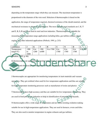
Sensors Insert Insert TABLE OF CONTENTS Thermocouples ---------------------------------------------------------------------------------------3 I. Beaded wire thermocouple -------------------------------------------------------------------------4 II. Thermocouple probe --------------------------------------------------------------------------------4 III. Surface probe -----------------------------------------------------------------------------------------5 2. Resistance temperature detectors ------------------------------------------------------------------5 I. Two-wire configuration -----------------------------------------------------------------------------7 II. Three-wire configuration ---------------------------------------------------------------------------7 III. Four wire configuration -----------------------------------------------------------------------------7 3. Thermistors -------------------------------------------------------------------------------------------8 I. Negative temperature coefficient thermistor -----------------------------------------------------8 II. Positive temperature coefficient thermistor ------------------------------------------------------9 4. Rainfall sensors --------------------------------------------------------------------------------------9 I. Expansion disk model -------------------------------------------------------------------------------9 II. Electrical conductivity sensor --------------------------------------------------------------------10 III. Water weight model -------------------------------------------------------------------------------10 IV. Rain gauges -----------------------------------------------------------------------------------------10 a. Standard rain gauge --------------------------------------------------------------------------------11 b. Weight rain gauge ----------------------------------------------------------------------------------11 c. Tipping bucket rain gauge ------------------------------------------------------------------------11 V. Vaisala RAINCAP ---------------------------------------------------------------------------------12 VI. Optical sensor ---------------------------------------------------------------------------------------13 Sensors Question 1 1. Thermocouple It is a voltage device that produces a voltage after there is a change in temperature of either of the spots with reference to the temperature in the other parts of the circuit system. The relationship between the output voltage of a thermocouple and the temperature is not linear and is usually estimated by a polynomial. Thermocouples are available in different calibrations depending on the temperature range which they can measure. The maximum temperature is proportional to the diameter of the wire used. Selection of thermocouples is based on the application, the range of temperature required, chemical resistance of the sheath material, and the mechanical resistance to abrasion and vibration. The most common used standards are J, K, T and E. B, S, R and K are used in steel and iron industries. Thermocouples are suitable for measuring high temperature range applications including kilns, gas turbine exhaust, diesel engines and other industrial applications (Pollock, 1991, p. 215) calibration J K T R S N B L Temperature range(°C) -200 to 1000 0 to 1260 -200 to400 0 to 1760 0 to 1760 0 to 1760 0 to 1760 0 to 500 (Ibrahim, 2002, p. 66) K thermocouples are appropriate for testing temperatures in processing plants such as petroleum refineries and chemical production plants. They are also appropriate for the tests of heating appliance safety. J thermocouples are appropriate for monitoring temperatures in inert materials and vacuum operations. They get oxidized when used for low temperature applications and thus are suitable for high temperature monitoring processes such as manufacture of resins and plastics T thermocouples have high accuracy and thus are suitable for low temperature monitoring. They are used in food processing industries to help in identification of potential food hazards. N thermocouples offer a wide range of temperature and are stable resisting oxidation making suitable for use in high temperature applications. They are used in furnaces, ovens and kilns. They are also used to monitor temperature in engine exhausts and gas turbines. Types of thermocouples I. Beaded wire thermocouple It is the smallest thermocouple consisting of two pieces of dissimilar wires that are held together through a welded bead. The welded bead is easily corroded or oxidized when used with liquids. It relies on a direct connection to an electrical circuit to accurately measure the temperature. They are small with fast response time making them a suitable choice for measuring gas temperature. II. Thermocouple probe Has a wire that is housed inside a metallic tube. The metallic tube serves as a sheath and is made up of materials such as stainless steel and Inconel. Inconel supports a higher temperature range while stainless steel is suitable for a wider range of chemical compositions. The tip of the probe may be grounded, ungrounded or exposed. The grounded tip keeps contact with the sheath to provide quick response time. A layer of insulation separates the tip from the sheath in ungrounded junctions. In an exposed junction, the tip extends to protrude outside the sheath and is best suited for air measurements. III. Surface probe They are made flat and thin for maximum contact between their surfaces and the rigid solid surface to help in surface temperature measurement of moving surfaces. They ensure accurate measurements by keeping the measuring area of the sensor in contact with the surface. 2. Resistance Temperature Detectors They are resistance devices that produce resistance due to a change in temperature. Its also called a resistance thermometer. Changes in temperature are converted to changes in electrical resistance that is they act as transducers. When current passes through a resistance temperature detector element, it produces a resistance value that is measured by an instrument and then interrelated to the surrounding temperature in the circuit. Constant current is applied across the resistor and the voltage drop measured to calculate the value of resistance. A resistance temperature director uses platinum; nickel or copper and Balco alloys for the elements (Fraden, 2004, p. 528). Element Temperature range(°C) Nickel -100 to 260 Platinum -200 to 800 Balco -100 to 204 The temperature measured is linear to the change in resistance. Resistance temperature detectors are more accurate than thermocouples and give stable values of temperature over a wide temperature range. Elements used for the detectors are classified according to their resistance at 0°C. The most common used detectors show a resistance of 100 Ohms at zero degrees Celsius. The most commonly used detector elements are made from platinum. Platinum is suitable because it is chemically inert that is it can withstand corrosion and oxidation, exhibits a linear relationship between the temperature and the resistance, offers a wide range of temperature and has high precision. Resistor temperature detectors are best suited for the measurement of temperature in Exhaust gas monitoring, Air, gas and liquid monitoring, plastics processing, in automotive for air and oil monitoring, in petrochemicals, and in heating ventilation and air conditioning equipments. Resistance temperature detectors may be constructed using wire wound or thin film configurations. A wire wound configuration has an inner coil detector with resistive coil that goes through a hole in a ceramic insulator or an outer coil with a resistive insulated material wound on a ceramic or glass. Thin film detectors have a thin stratum of resistive matter that is deposited on a ceramic substrate and then trimmed to the required resistance value. A thin layer of glass is added for protection. Lead wires are welded to the sensor pads and covered with a sheath such as glass. Thin film detectors are preferred because they are less expensive, have high vibration resistance and have better response times than to the wire wound detectors. Resistance temperature detectors provide high accuracies over a wide range of temperature. They have high degrees of stabilization and standardization. They are used to monitor temperature in food processing plants, textile production, processing of hydrocarbons, fluid temperature measurement and processing of plastics. They are also used in engine exhausts and stoves. Lead wire configurations have 2, 3 or 4 wires that extend from the sensor and selection on the number of wires is based on the required accuracy, stability, environmental conditions, the location of the receiving device, and the sensor range and resistance I. Two-wire configuration It features two wires to build a simple and less expensive configuration than the other wire configurations. Each wire provides a connection to the ends of the sensor and uses a single current source. The configuration is suitable where the lead wire resistance is considered as an additive constant in the circuit, and the effects of ambient temperature change can be ignored. The configuration is used when high accuracy is not preferred. The lead wires provide additional series resistance which leads to errors in measurements. It allows up to 100meters of cable. II. Three-wire configuration It uses two current sources and an additional lead wire to eliminate the lead and terminal contact resistances that occur in a two-wire circuit. It is the most commonly used configuration and gives accurate measurements of temperature. It allows up to 600 meters of cable. III. Four-wire configuration It eliminates the problems arising due to the length of extension wires and the resistance imbalance between the leads. Lead resistance is also eliminated and hence smaller gauge wires can be used. The configuration is suitable for a wide range of applications exposed to corrosive conditions, with some distance between the sensor and the receiving device that require high accuracy. 3. Thermistors Thermistor is a temperature sensor element composed of semiconductor material that is highly sensitive to a small change in temperature. They use ceramics, polymers or metal oxides including cobalt, iron, manganese, copper and titanium. The resistance of a thermistor is inversely proportional to the change in temperature since they have negative temperature coefficients. The resistance can be 100 Ohms or more per degree change in temperature. They are used for low temperature range measurements due to the reducing resistance with an increase in temperature but give accurate results within the ranges that they work. The temperature range for a thermistor is between -90°C and 130°C (Fraden, 2004, p. 532) A thermistor is a simple resistor with an added property of temperature sensitivity making it cheaper than all other temperature sensors and easier to insulate. They can also work at any voltage and the amplifier is not required to read minute values. Thermistors have high mechanical resistance and are chemically stable making them more reliable than Thermocouples and the Temperature resistant detectors. Thermistors are classified according to the attachment of electrodes to the ceramic encapsulation as Negative temperature coefficient and positive temperature coefficient. I. Negative temperature coefficient thermistors Materials used to make Negative temperature coefficient thermistors include rods, plates, pressed disc and cast chips of semiconductors. The temperature impacts the resistance negatively to increase the number of charge carriers to conduct more current and the relationship is shown by an exponential curve. They have higher temperature sensitivity than other temperature sensors. They are used in limiting Current in power supply circuits, monitoring temperature in incubators and temperature surveillance applications. II. Positive temperature coefficient thermistors They are made using compositions of lead, barium and strontium titanates with yttrium, manganese or silica added. They are used as resettable fuses to protect against high current conditions. They have self heating characteristics making them suitable for liquid level monitoring, constant current applications, time delay and arc suppression applications Time delay applications include the use as timers in CRT screens and television sets. Question 2 4. Sensors for measurement of rainfall Rainfall sensors are switching devices that are activated by rainfall and are classified according to the application into water conservation devices and automotive sensors used in automobiles for protection of the interior. Rain sensors are available in the following designs including electrical conductivity, water weight and expansion disk types. In water conservation, the sensors disconnect power to save water I. Expansion disk model The expansion disk model features a hygroscopic disk connected to an electric switch. The disk swells in the presence of rain to press the switch and shrinks as the rain dries out to release the switch. The sensor is connected to the terminals of the irrigation controller sensor. The sensor may also be connected in series with the solenoid valve common circuit. Expansion disk sensors are preferred since they dont need frequent cleaning A freeze sensor may also be installed to the irrigation system to stop operation at freezing temperatures. Rain sensors are suitable for use in places whose temperatures do not go beyond freezing points. II. Electrical conductivity sensors They also use a rainwater collection dish. The system is connected to two electrodes that switch the system after contact is made with the collected water. The collected water rises to a preset level to complete the circuit and shut the system down. Once the water has evaporated and dropped down the preset level, the circuit opens to return the irrigation system into operation. III. Water weight model It uses a small dish that is attached to the main controller of the irrigation system. Rainwater collects to a specific set point to trigger the controller that turns the water valve off. The evaporation of water in the dish is proportional to the drying time of the soil. Once the water level goes below the set point, the controller turns the valve back. IV. Rain gauge Ii is an instrument that measures the amount of rainwater for a set period and mostly measures rain in millimeters and may also be reported in inches or centimeters. Rain gauges have drawbacks including that they are unreliable for collection of data in a hurricane; they only show data for a localized area. Rain gauges do not give accurate measurements of the rainfall since droplets tend to stick on the sides of the collecting device. While freezing temperature conditions, ice may collect on the funnel of the collecting device to block any subsequent rain to pass through. Water collected from roofs may collect in the gauge to give inaccurate readings and thus, they should be placed in the open away from obstacles such as buildings and trees. a. Standard rain gauge (Cloud Tracker Weather Instrument, n.d) It consists of a funnel that collects water into the transparent glass bottle. The level of water is read against a calibrated scale to estimate the amount of rainfall. The outer cylinder protects the glass bottle from mechanical damage. Oil is also added to the bottle, and floats on the water surface to prevent evaporation. An amount of water equal to the added oil is subtracted when readings are being taken. b. Weighing rain gauge A container that rests on a scale collects precipitation to record the weight on a revolving graph paper or by using a vibrating wire that is attached to a data logger. It can be used to measure other forms of precipitation include snow, hail and rain. Weighing rain gauges require higher maintenance and are more expensive than tipping bucket gauges (Teegavarapu, 2012, p. 12) c. Tipping bucket rain gauge It consists of a pivoted bucket that is divided into two compartments. When compartment one fills with the precipitate, it tips to dump water into the second compartment. Every time the bucket tips, a circuit is completed and mark records on a moving paper. The tipping bucket easily shows the character of the rain that may be light, medium or heavy rain. It is less accurate than a standard rain gauge since rain may stop before the lever has tipped (Teegavarapu, 2012, p. 11) V. Vaisala RAINCAP The Vaisala RAINCAP has a smooth stainless surface which measures the impact of an individual droplet using a piezoelectric sensor located beneath the steel cover. The sensor can distinguish between hail and rain, and real time data on the intensity, duration of accumulated rainfall is also achieved The RAINCAP does not require maintenance and has no moving parts. The RAINCAP gives more accurate values than the tipping bucket gauges. They can be used in remote locations since they require no maintenance. Structure of RAINCAP sensor retrieved April 1, 2014 from www.vaisala.com Raindrops fall on the sensor at different diameters and velocity to produce acoustic signals that are then converted into voltages by the piezoelectric detector. Total rainfall is then calculated from the voltage signals per unit time and the surface area of the sensor. Intensity and duration of rain is also calculated from the obtained data. VI. Optical sensor It uses beams of infrared light to sense water on its outside and is highly sensitive but immune to false trips. It is also completely closed and thus its conductors are not exposed to corrosion. They are used to measuring rainfall and or to close skylights during rain. Image of a Hydreon Optical rain sensor retrieved April 1, 2014 from www.rainsensors.com. There is a great need for sensors that provide accurate measurements of rain even when poor weather conditions such as hurricanes and strong winds. Typical rain gauges do not provide accurate measurement of rainfall. They do not have corrosion resistance and are easily worn out requiring maintenance. The measurement of precipitation is significant for a wide range of applications including water resource management, climatology, metrology, hydrology and satellite precipitation estimates. High precision instruments are required for the measurement of rainfall, and newer sensors are being developed and adopted to help in the achievement of accurate data for precipitation. References Cloud Tracker Weather Instrument. (n.d.). Science Learning Space Physics Category. Retrieved April 1, 2014, from https://www.sciencelearningspace.com/category/ecamp/ecamp- physics-lab/ecamp-physics/ Fraden, J. (2010). Temperature sensors. Handbook of modern sensors physics, designs, and applications (3rd ed., pp. 519-568). New York: AIP Press/Springer. Retrieved April 1, 2014 from http://books.google.co.uk/books?id=W0Emv9dAJ1kC&printsec=frontcover&dq=Handbo ok+of+modern+sensors+physics,+designs,+and+%09applications&hl=en&sa=X&ei=r31 DU9hFx4DLA- eagZAE&ved=0CDUQuwUwAA#v=onepage&q=Handbook%20of%20modern%20sens ors%20physics%2C%20designs%2C%20and%20%09applications&f=false Hydreon Optical Rain Sensor - Model RG-11. (n.d.). Hydreon Optical Rain Gauge / Rain Sensor RG-11. Retrieved April 1, 2014, from http://www.rainsensors.com Ibrahim, D. (2002). Thermocouple temperature sensors. Microcontroller-based temperature monitoring and control (pp. 63-105). Oxford: Newnes. Retrieved April 1, 2014 from http://books.google.co.uk/books?id=oth6rDhSKiwC&printsec=frontcover&dq=Microcon troller- based+temperature+%09monitoring+and+control&hl=en&sa=X&ei=d31DU_avGISCzA O_44LYBA&ved=0CE0QuwUwAA#v=onepage&q=Microcontroller- based%20temperature%20%09monitoring%20and%20control&f=false Pollock, D. D. (1991). Standard thermo elements. Thermocouples: theory and properties (pp. 215-258). Boca Raton, Fla.: CRC Press. Retrieved April 1, 2014 from http://books.google.co.uk/books?id=_CK8U_bzgKQC&printsec=frontcover&dq=isbn:08 49342430&hl=en&sa=X&ei=THFDU9LDH6LP0QXs1oA4&redir_esc=y#v=onepage&q &f=false Teegavarapu, R. S. (2012). Precipitation measurement. Floods in a changing climate (pp. 10-32). Cambridge: Cambridge University Press. Retrieved April 1, 2014 from http://books.google.co.uk/books?id=KJa6tEGMzwQC&printsec=frontcover&dq=Floods +in+a+changing+climate&hl=en&sa=X&ei=NH5DU- zdDIK8ygPlkYJw&ved=0CEAQuwUwAA#v=onepage&q=Floods%20in%20a%20chan ging%20climate&f=false Vaisala RAINCAP sensor technology (n.d.). Vaisala RAINCAP sensor technology. Retrieved April 1, 2014, from http://www.vaisala.com/Vaisala%20Documents/Technology%20Descriptions/RAINCAP _Technology.pdf Read More
Cite this document
  • APA
  • MLA
  • CHICAGO
(Beaded Wire Thermocouple Assignment Example | Topics and Well Written Essays - 2500 words, n.d.)
Beaded Wire Thermocouple Assignment Example | Topics and Well Written Essays - 2500 words. Retrieved from https://studentshare.org/physics/1636627-sensors
(Beaded Wire Thermocouple Assignment Example | Topics and Well Written Essays - 2500 Words)
Beaded Wire Thermocouple Assignment Example | Topics and Well Written Essays - 2500 Words. https://studentshare.org/physics/1636627-sensors.
“Beaded Wire Thermocouple Assignment Example | Topics and Well Written Essays - 2500 Words”, n.d. https://studentshare.org/physics/1636627-sensors.
  • Cited: 0 times

CHECK THESE SAMPLES OF Beaded Wire Thermocouple

The Main Temperature Sensors for Control Systems

This research explores three basic types of sensors: RTD, thermocouple, and Thermistors.... Ibrahim and Coupland confirm that the thermocouple sensors are used in applications that handle very high temperatures such as incinerators.... A thermocouple is a temperature transducer, which operates on a principle that unlike conductive materials is capable of generating current when they are joined (Setback effect) (Jianwei Shen & Shen, 2009)....
8 Pages (2000 words) Assignment

Thermodynamics and Heat Transfer

Add some water to the heating beaker and immediately place the relevant specimen in the water.... Place the beaker under moderated and uniformed heat for about five minutes.... Put down that particular water temperature (t2) (An assumption is made that the specimen temperature is… The concluded experiment was not prospective as expected due to a higher error percentage....
3 Pages (750 words) Lab Report

Integrated Technology Systems

This discussion presents a review of the main temperature sensors for control systems; thermocouples, Resistance Temperature Detectors (RTD) and thermistors outlining the characteristics of each type and providing an explanation and examples of the types of systems they are most suited to.... hellip; This paper also provides a summary of the typical sensors for measurement of rainfall....
13 Pages (3250 words) Assignment

Small Scale Compartment Fire

There is a relationship between the effect of temperature and time to ignition 2 Methodology This experiment utilizes a firebox and a thermocouple.... As the paper "Small Scale Compartment Fire" outlines, in a scenario where the flame exhaust occurs through an opening, it takes place through ventilation that is controlled....
10 Pages (2500 words) Lab Report

Fire Effect on Natural Ventilation in Compartments

"Fire Effect on Natural Ventilation in Compartments" paper establishes fire effect on natural ventilation in compartments through experimentation and verifications through CFAST simulations and depicts the achievable smoke conditions and their effects on tenability of a two storey building.... hellip; The pressure is noted to fall with respect to the temperature of the room since the volume of air increases due to expansion....
7 Pages (1750 words) Term Paper

Experiment Which Allows Students to Develop an Understanding of Compartment Fires

… ©2016Aims (5 marks)The experiment allows students to develop an understanding of compartment fires.... The aim of this experiment is to assess how a compartment fire develops from ignition to flashover and decay.... The primary objective of the research ©2016Aims (5 marks)The experiment allows students to develop an understanding of compartment fires....
6 Pages (1500 words) Assignment

The Development of Compartment Fires Understanding

While one thermocouple was installed on the protruding area on the floor hole, the remaining ones were deployed on the rear wall of the experimental compartment setup.... … Part A.... (LO 1-3) Experiment Write-upAimsThe aims of this experiment are derived from the fact that compartment fires experience various stages or phases....
15 Pages (3750 words) Assignment

Heat Transfer, Fluid Dynamics, Fire Plume and Enclosure Fire

… – The temperature of the hotter surface – The temperature of the colder surface (ambient temperature)– Thickness of the board = Heat flux () = [b] Calculation of the temperature of the two faces of the wall(i)Heat flux)Where: - Heat transfer The paper "Heat Transfer, Fluid Dynamics, Fire Plume and Enclosure Fire" is a good example of an assignment on science....
12 Pages (3000 words) Assignment
sponsored ads
We use cookies to create the best experience for you. Keep on browsing if you are OK with that, or find out how to manage cookies.
Contact Us