StudentShare
Contact Us
Sign In / Sign Up for FREE
Search
Go to advanced search...
Free

Speed Improvement of Aerofoils to an F1 Car - Book Report/Review Example

Cite this document
Summary
"Speed Improvement of Aerofoils to an F1 Car" paper introduces concepts of angular acceleration, moments of forces, scaling and dimensioning, coefficient of friction, unit conversion, and problem-solving. The research involves the calculation of the maximum speed with and also without aerofoils…
Download full paper File format: .doc, available for editing
GRAB THE BEST PAPER98.2% of users find it useful
Speed Improvement of Aerofoils to an F1 Car
Read Text Preview

Extract of sample "Speed Improvement of Aerofoils to an F1 Car"

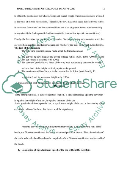
Speed Improvement of Aerofoils to an F1 Car Affiliation Speed Improvement of Aerofoils to an F1 Car Introduction This research paper introduces concepts of angular acceleration, centripetal force, moments of forces, scaling and dimensioning, coefficient of friction, unit conversion, and problem solving. The research involves the calculation of the maximum speed with and also without aerofoils. ‘Foilsim’ software is used in the research to aid in solving the problem of what speed improvement do aerofoils give to an F1 car. Firstly, the maximum speed of the car around the four bend radii (of 50m, 100m, 200m and 500m) without the aerofoils, for each of the four tyre conditions is calculated. Next, in order to determine the chord and span of each aerofoil, a Google image search is performed to come up with a top view of an F1 car, and using the maximum width (approx. 1.8 m) as a scaling reference, the dimensions of the car are measured. Then the image is copied into the Ms-word programme and measured to obtain the positions of the wheels, wings and overall length. These measurements are used as the basis of further calculations. Thereafter, the new maximum speed for each bend radius is calculated for each of the four tyre conditions and a set of graphs plotted which concisely summarise all the findings (with / without aerofoils, bend radius, tyre friction coefficient). Finally, the forces for one particular corner radius / tyre combination are calculated when the car is without aerofoils and further determined whether if the front or the back tyres slip first. The task of the Research The following assumptions are made about the formula one car: 1. The car will be travelling around a bend of fixed radius: (50m / 100m / 200m / 500m) 2. The car’s mass is assumed to be 620kg 3. The centre of gravity is two thirds of the way back horizontally between the wheels and one third of the height vertically up from the ground 4. The maximum width of the car is also assumed to be 1.8 m (as defined by F1 regulations) and its maximum height to be 0.95m. The entire task shall be handled as outlined in the introduction above. Discussion Where; is the centripetal force, is the coefficient of friction, is the Normal force upon the car which is equal to the weight of the car., is equal to the mass of the car is the gravitational force upon the car, is equal to the weight of the car, is the velocity of the car, is the radius of the bend that the car shall be negotiating From the above derivation, it is apparent that velocity is affected by the radii of the bends, the frictional coefficients and the gravitational pull upon the car. Thus, the velocity of the car is to be calculated based on the magnitude of the frictional coefficients and the radii of the bends. 1. Calculation of the Maximum Speed of the car without the Aerofoils i. Velocity Calculation for the Intermediate tyres in the dry with Frictional Coefficient of 0.7 For the bend radius of 50m, For the bend of radius 100 m, For the bend of radius 200m, For the bend of radius 500 m, ii. Velocity Calculation for the Intermediate tyres in the wet with Frictional Coefficient of 0.4 For the bend radius of 50m, For the bend of radius 100 m, For the bend of radius 200m, For the bend of radius 500 m, iii. Velocity Calculation for Slicks in the dry with Frictional Coefficient of 0.9 For the bend radius of 50m, For the bend of radius 100 m, For the bend of radius 200m, For the bend of radius 500 m, iv. Velocity Calculation for Slicks in the wet with Frictional Coefficient of 0.1 For the bend radius of 50m, For the bend of radius 100 m, For the bend of radius 200m, For the bend of radius 500 m, 2. Calculation of the Maximum Speed of the car with the Aerofoils The primary function of the aerofoils is to create a down force, that aids in pushing the tyres of the car onto the track and consequently improve the cornering forces; and minimise the drag that is brought about by turbulence and finally act to slow the car down (Formula1, 2014). Using the aerofoil software, the lift force, equivalent to the down force in Formula 1 cars, is equal to for an aerofoil of span and chord of. Thus, the total down ward force is equal to the value of the weight of the car, , and the aerofoil down force of . In this case, the centripetal force, , is directly proportional to the resultant upward force on the car as a result of the two down ward forces, and not merely the weight of the car as earlier calculated. The use of the moment of forces can be utilised to come up with the resultant upward force. The turning point of the moments is taken to be at the front of the car. The down force is assumed to be acting at the rear of the car and the resultant upward force at the centre of gravity (COG) of the car. The diagram 1 in the appendix clearly shows the positions of the said forces, as the overall car length is assumed to be 4.5 m. The principle of the moment of forces states that when a system is “in equilibrium the total sum of the anti-clockwise moment is equal to the total sum of the clockwise moment”. Simply put, this principle implies that, at a point; In the case above, the clockwise moments are the ones comprising of the weight and down force, both acting at the centre of gravity and the rear part of the car respectively. The anticlockwise moment is composed of the resultant upward force on the car. Hence, the whole system becomes; Therefore, the resultant upward force is equal to; . From the previous formula, i. Velocity Calculation for the Intermediate tyres in the dry with Frictional Coefficient of 0.7 For the bend radius of 50m, For the bend of radius 100 m, For the bend of radius 200 m, For the bend of radius 500 m, ii. Velocity Calculation for the Intermediate tyres in the wet with Frictional Coefficient of 0.4 For the bend radius of 50m, For the bend of radius 100 m, For the bend of radius 200 m, For the bend of radius 500 m, iii. Velocity Calculation for Slicks in the dry with Frictional Coefficient of 0.9 For the bend radius of 50m, For the bend of radius 100 m, For the bend of radius 200 m, For the bend of radius 500 m, iv. Velocity Calculation for Slicks in the wet with Frictional Coefficient of 0.1 For the bend radius of 50m, For the bend of radius 100 m, For the bend of radius 200 m, For the bend of radius 500 m, Forces at a bend of radius 100 m for the various tyre conditions Therefore, the centripetal force,, for the intermediate tyres in the dry of the coefficient of friction, of 0.7 is; The centripetal force,, for the Intermediate tyres in the wet of the coefficient of friction, of 0.4 is; The centripetal force,, for the Slicks in the dry of the coefficient of friction, of 0.9 is; The centripetal force,, for the Slicks in the wet of the coefficient of friction, of 0.1 is; Since there is no net force in the vertical direction, N is assumed to W, weight of the car and it is given by the, (Waynes, 2014) The coefficient of friction can be calculated from the formula derived below. The coefficient of friction is the minimum value for any system. If is any smaller than this, then there won’t be adequate force towards the centre of the circle for the car to follow the curve and it will slip (Roylance, 2000). The coefficient of friction can be decreased by decreasing the speed of the car or increasing the radius of the bend (Rana & Kaushik, 2014). And since the centre of gravity is 2/3 rds way back horizontally between the wheels, the rear wheels will slip first as the centre of gravity is inclined to the rear part of the car. Conclusion In the first case (speed of the car without the aerofoils), the speed of the car is influenced by the radius of the bend, coefficient of friction and the gravitational acceleration. As either the radius of the bend or coefficient of friction increases, the speed of the car also increases. Hence, the speed of the car is directly proportional to the radius of the bend and the coefficient of friction. On the other hand, in the second case (speed of the car with the aerofoils), the speed of the car is influenced by the radius of the bend, coefficient of friction and the mass of the car. In this car the speed of the car is inversely proportional to its mass; as the mass increases, its speed decreases and vice versa. On the other hand, the car’s speed is directly proportional to the radius of the bend and the coefficient of friction; speed increases with an increase in the radius of the bend and coefficient of friction. References De Groote, S. (2009, May 14). Aerodynamics in racing - F1technical.net. Retrieved December 22, 2014, from http://www.f1technical.net/articles/10 Jim Clark Foundation. (1969). Aerofoil report: A study of the aerodynamic characteristics of racing cars fitted with aerofoils. London: Jim Clark Foundation. Leslie-Pelecky, Diandra L. 2008. The physics of NASCAR: how to make steel + gas + rubber = speed. New York: Dutton. Pelican Technical Article: Physics of Racing Series. (n.d.). Retrieved December 23, 2014, from http://www.pelicanparts.com/techarticles/physics_racing/ Rana, A & Kaushik, P, S. 2014. Increasing Down force in High- speed Motorcycle Specially during Cornering. International Journal of Applied Engineering Research, Volume 9, Number 5 (2014) pp. 559-566 Roylance, D. 2000. Statics of Bending: Shear and Bending Moment Diagrams. The US: Massachusetts Institute of Technology Waynes, 2014. Cars and Their “Cornering” Ability. Retrieved from < http://www.mrwaynesclass.com/circular/notes/corner/home.htm> Accessed on 24th Dec, 2014 Appendix Diagram 1 Up ward Force, 3m 4.5m Mg (Weight) Top View of the F1 Car Read More
Cite this document
  • APA
  • MLA
  • CHICAGO
(“Aerofoils - What Speed Increase do Aerofoils Give to an F1 Car Book Report/Review”, n.d.)
Aerofoils - What Speed Increase do Aerofoils Give to an F1 Car Book Report/Review. Retrieved from https://studentshare.org/miscellaneous/1672905-aerofoils-what-speed-increase-do-aerofoils-give-to-an-f1-car
(Aerofoils - What Speed Increase Do Aerofoils Give to an F1 Car Book Report/Review)
Aerofoils - What Speed Increase Do Aerofoils Give to an F1 Car Book Report/Review. https://studentshare.org/miscellaneous/1672905-aerofoils-what-speed-increase-do-aerofoils-give-to-an-f1-car.
“Aerofoils - What Speed Increase Do Aerofoils Give to an F1 Car Book Report/Review”, n.d. https://studentshare.org/miscellaneous/1672905-aerofoils-what-speed-increase-do-aerofoils-give-to-an-f1-car.
  • Cited: 0 times

CHECK THESE SAMPLES OF Speed Improvement of Aerofoils to an F1 Car

Aircraft and automotive system

The effort here is to explain how much speed improvement dos airfoils give to an f1 car.... Also the software Foilsim III has been used to understand various aspects of aerofoils like the shape, span and chord, geometry and so on.... The different speed limits of the car is given along with car mass, width and height of car, centre of gravity and tyres friction.... Here , in this paper, different tyre conditions are given and with this the maximum speed of the car with and without aerofoils need to be calculated....
8 Pages (2000 words) Book Report/Review

Airfoils in the Speed of F1 Cars

The main objective of this project is to analyze the properties and demonstrate the effects of aerofoils on the speed improvement of F1 cars.... The paper "Airfoils in the Speed of F1 Cars" states that the aerofoil is an improvement to the racing car's speed as it goes round the corners.... The question that every driver of the racing formula 1 car asks is about the maximum speed that the car requires, which is ensured by adding the aerofoil....
9 Pages (2250 words) Book Report/Review

Improving the Efficiency of Wind Turbine Blades

o achieve sustainability in the energy sector, wind energy is achieving significant improvement such as horizontal axis wind turbine (HAWT) which is reducing system expenses per kW of the generated power and increasing the power production.... "Improving the Efficiency of Wind Turbine Blades" paper tries and finds out new methods of improving wind turbine efficiency by developing new surface material that increases the drag coefficient so that the fan blades can catch a lower speed of the wind....
8 Pages (2000 words) Research Proposal

Techniques to Produce Typical Engineering Products

Here the blades are supposed to operate at a constant speed and a constant pitch angle.... gearbox: This is used to synchronize the rotor speed to that of the generator.... In order to be cost-effective, a 10 KW wind turbine will require an average minimum wind speed of 4.... igure: Relationship between wind speed and wind power(Source: www.... As a matter of fact, the power derived from the wind is proportional to the cube of its speed....
6 Pages (1500 words) Term Paper

Aerofoils - What Speed Increase do Aerofoils Give to an F1 Car

The paper "Aerofoils - What Speed Increase do Aerofoils Give to an f1 car?... The paper "Aerofoils - What Speed Increase do Aerofoils Give to an f1 car?... The paper "Aerofoils - What Speed Increase do Aerofoils Give to an f1 car?... y introducing aerofoils on an f1 car, the innovators were however motivated by the fact that this aids in a virtual increase of weight thus giving it the required stability while considerably increasing the speed on the track....
8 Pages (2000 words) Assignment

Aerodynamic: Formula 1

This laboratory assignment, therefore, sought to investigate the speed increments that come with the introduction of aerofoils by utilizing such concepts as the coefficient of friction, centripetal force, angular acceleration, unit conversion, aerofoil lift, moments of forces, Newton's laws, scaling and dimensioning, estimation and problem-solving.... The most important concerns to the modern aerodynamic designers have always been identified as minimization of drag through streamlining and creation of downforce to ensure the car does not veer off the track....
7 Pages (1750 words) Report

Forces That Affect the Movement of an Aircraft and the Aerodynamic Behavior

The results were used as a model of how aerofoils of aircraft behave when the aircraft is in flight.... Lift is caused by a change in the air that causes a change in pressure between the atmosphere and the immediate surroundings of the aerofoils (Clancy, 1975).... The shape and size of the aerofoil will dictate the level of form drag with aerofoils' large cross-sections having proportionally large form drag while thin ones will have lower drag force....
12 Pages (3000 words) Term Paper

What Speed Improvement Do Aerofoils Give to an F1 Car

"What Speed Improvement Do Aerofoils Give to an f1 car" paper argues that the principles used to obtain the unique characteristics of f1 cars has been defined clearly in this paper.... The aerodynamic setups of an f1 car can be varied to suit the race tracks as with regards to the track length in the straights and the nature of corners on the track.... At 500m radius corners, the f1 car is capable of moving at as much speed as that on a straight racecourse....
6 Pages (1500 words) Coursework
sponsored ads
We use cookies to create the best experience for you. Keep on browsing if you are OK with that, or find out how to manage cookies.
Contact Us