StudentShare
Contact Us
Sign In / Sign Up for FREE
Search
Go to advanced search...
Free

Engineering Environmental Sustainability- Take Home FINAL EXAM - Assignment Example

Cite this document
Summary
As shown in Fig. 13-53, the piles will be installed through a 10-m- thick, natural clay layer with ( Su/σ’v)NC= 0.25 into a sand layer with energy corrected, normalized below counts N60…
Download full paper File format: .doc, available for editing
GRAB THE BEST PAPER96.3% of users find it useful
Engineering Environmental Sustainability- Take Home FINAL EXAM
Read Text Preview

Extract of sample "Engineering Environmental Sustainability- Take Home FINAL EXAM"

13-14, pages 507- 520=13 Both Closed-end steel pipe piles and drilled shafts are under consideration in a project. As shown in Fig. 13-53, the piles will be installed through a 10-m- thick, natural clay layer with ( Su/σ’v)NC= 0.25 into a sand layer with energy corrected, normalized below counts N60 of 25, 29, 32, 40, 42 and 45 for the 6m into unit layer. Sand has unit weight equal to 20 kN/ m3, and the clay has unit weight equal to 17kN/m3. The critical- state friction angle of the sand is 320 and K0= 0.45. The water table is at the surface.

In the past the soil profile had been subjected to uniform surcharge of 50kPa applied on the surface of soil deposit, which was later removed causing both the sand and clay layers in the current states to be over consolidated. For a 15-m- long, 500-mm drilled shaft and a geometrically identical closed-end steel pipe pile, calculate (a) the shaft capacity due to the clay layer ( divide the clay into ten sub layers of equal thickness in your calculations), (b) The shaft capacity due to the sand layer, (c) the total shaft capacity, (d) the ultimate base capacity, (e)the ultimate load capacity of the pile, (f) the allowable load based on a suitable factor of safety (without consideration of the strength of the pile cross-section), and (g) the allowable load if the compressive strength of the concrete is 15 MPa.

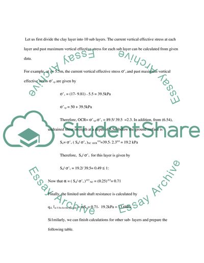
Figure 13-53 Pile and soil profile for problem 13-14SOLUTION:(a) The shaft capacity due to the clay layerClosed end pipe pile Let us first divide the clay layer into 10 sub layers. The current vertical effective stress at each layer and past maximum vertical effective stress for each sub layer can be calculated from given data.For example, at z= 5.5m, the current vertical effective stress σ’v and past maximum vertical effective stress σ’vp are given byσ’v = (17- 9.81) ˣ 5.5 = 39.

5kPaσ’vp = 50 + 39.5kPaTherefore, OCR= σ’vp/ σ’v = 89.5/ 39.5 =2.3. In addition, from (6.54), undrained shear strength at a depth of 5.5m below the ground surface isSu= σ’v ( Su/ σ’v )NC OCR 0.8=39.5ˣ 2.30.8 = 19.2 kPaTherefore, Su/ σ’v for this layer is given by Su/ σ’v = 19.2/ 39.5= 0.49 ≤ 1:Now that α = ( Su/ σ’v )-0.5 NC = (0.25)-0.5= 0.71Finally, the limited unit shaft resistance is calculated by qsL ǀat 5.5m for the pipe pile = αSu = 0.71ˣ 19.2kPa = 13.

6kPaSi1milarly, we can finish calculations for other sub- layers and prepare the following table.S- Table 13-9LayerZtout(m)Zbot (m)MidDepth(m)Δhi(m) σv’(kPa)σ vp’(kPa) OCRSu(kPa)αSu/ σ’vαqsLi(kPa)qsLiΔhi (kN/m)1010.513.653.614.97.82.1704.13.23.22121.5110.860.85.610.70.990.505.45.43232.5118.068.03.813.10.730.597.77.74343.5125.275.2315.20.490.659.99.95454.5132.482.42.516.90.520.6911.711.76565.5139.589.52.319.20.490.7113.613.67676.5146.796.72.121.10.450.7515.815.88787.5153.9103.91.922.50.420.7717.317.39898.5161.1111.11.824.40.400.7919.319.3109109.5168.3118.31.726.10.380.8121.121.1 Σ qsLi Δhi =125.

0 kN/mTherefore, the shaft capacity of closed- ended pipe pile due to clay later is Qsl= Σ qsLiAsi = ∏BΣ qsLi Δhi= ∏ 0.5mˣ125kNm =196.3 ˣ 196 kN answer to (a) Drilled shaftThe value α is calculated from (13.50). For example, the value α for the 3rd layer is calculated by α =0.4 [1-0.12ln(su/ pa)]= 0.4 [1-0.12ln(13.1/1oo)]= 0.50Now, we can simply prepare the following table: S- Table 13-10LayerZtot(m)Zbot (m)midDepth(m)Δhi(m) σv’(kPa)σ vp’(kPa) OCRSu(kPa)αSu/ σ’vαqsLi(kPa)qsLiΔhi (kN/m)1010.513.653.614.97.80.524.14.14.12121.5110.860.85.610.70.510.505.55.53232.5118.068.03.813.10.500.596.66.64343.5125.275.2315.20.490.497.47.45454.5132.482.42.516.90.520.498.38.36565.5139.589.52.319.20.490.489.29.27676.5146.796.72.121.10.450.479.99.98787.5153.9103.91.922.50.420.4710.610.69898.5161.1111.11.824.40.400.4711.511.5109109.5168.3118.31.726.10.380.4612.012.

o Σ qsLi Δhi =85.1 kN/mNote that the same equation was used regardless of OCR values. The overall result is on the conservation side. Therefore, the shaft capacity of the drilled shaft due to the clay layer is qsl= Σ qsLiAsi = ∏BΣ qsLi Δhi= ∏ 0.5mˣ85.1Nm =133.7 ͌ 134 kNanswer(b) Shaft capacity due to the sand layerClosed- end pipe pileLet us first calculate the relative density of each soil layer. Using (7.6), for example, the relative density at z= 12.5m is calculated asσ’v= (17-9.81) ˣ 10+ (20-9.81) ˣ2.5 = 97.

4 kPaσ’v= 97.4 + 50= 147.4 kPaOCR= 147.4/ 97.4= 1.5 C= (Ko/ KoNC)=√OCR=√1.51= 1.22DR = 100√ [N60/ A+BC (σ’v/ PA)= 100√ 32/ 36.5 + 27 ˣ1.22 97.4/ 100 = 68.3%]σ ‘h=Koσ’v= 0.47ˣ 97.4kPa= 43.8kPaThe unit pile base capacity at z= 12.5m is calculated using (13.25):qbl= 1.64pA exp[0.1041Фc+(0.0264 – 0.0002Фc) DR]( σ ‘h/ PA)0.841- 0.0047DR=164exp[0.1041 ˣ32+(0.0264- 0.0002 ˣ32) ˣ168.3](43.8/100)0.841-0.0047 68.3= 11705.3kPa.Now, taking the interface friction angle between pile and soil as 0.

85Фc for the steel pile unit shaft capacity is calculated from (13.35):V qsL at 12.5m for the pipe pile = 0.02tanδ[ 1.02- 0.0051DR]qbL = 0.02ˣ tan (0.85ˣ 320)[ 1.02- 0.0051ˣ 68.3] 11705.3= 80.8kPaSimilarly, we can finish calculation for other sub- layers and prepare the following table. S- Table 13-11 Σ qsLi Δhi =412.9kN/mTherefore, the shaft capacity of closed-end steel pipe pile due to sand layer is.Qsl= Σ qsLiAsi = ∏BΣ qsLi Δhi= ∏ 0.5m 412.9kN/ m 640kN Answer to (b) The coefficient of lateral earth pressure K is calculated using (13.32).For example, at z= 125K= 0.

7Ko Experise [{o.0114- 0.0022ln [{0.0114- 0.0022ln(σ’v/ PA)} DR]= 0.7K0exp[{o.o114- 0.0022ln( 97.4]/ 100)} 68.3= 0.69Taking δ= Фc, the limit unit shaft capacity is calculated byqsL at 12.5m for drilled shaft =K σ’v tan δ= 0.67ˣ 97.4ˣ tan 32 = 42.kPaSimilarly we can finish calculations on other sub systems and following table:S-Table 13-12 Σ qsLi Δhi =213.4kN/mTherefore the fraction of the shaft capacity of the drilled shaft due to the sand layer is QsL = Σ qsLiAsi= ∏B Σ qsLi Δhi= ∏ˣ 0.5 ˣ 213.4= 335kNanswer to (b)(c)Total shaft capacityThe total shaft capacity is the sum of the shaft capacity due to the sand and clay layers.

Closed-end pipe pileQsL= QsL, CLAY + QsL, SAND= 196.3 + 648.6kN= 844.9 ͌845kNanswer to (c)(d) Based capacityClosed-end pipe pileWe will calculate the base capacity using soil variables. Let us first calculate relative density of soil layer below pile base. Using (7.6), the relative density at z=15m is calculated as σ’v= (17-9.81) ˣ 10+ (20-9.81) ˣ5 = 122.9kPaσ’vp= 122.9 + 50= 172.9kPaOCR= 172.9/ 122.9= 1.41 C= (Ko/ KoNC)=√OCR=√1.41= 1.19DR = 100√ [N60/ A+BC (σ’v/ PA)= [100√ 36.

5 + 27 ˣ1.19ˣ 122.9/ 100] =77%σ’h= K0 σ’v0.45ˣ 122.9kPa =55.3kPaThe limit unit pile base capacity at z= 15m is calculated using (13.25):QbL=164PAexp[0.1041Фc + (0.0264- 0.0002 Фc)DR]( σ’h/PA)0.841-0.0047DR =164expp0.1041 ˣ 32+ (0.0264- 0.0002 ˣ 32)77](55.3/100) 0.841-0.0047ˣ77=16110.9kPaThe ultimate unit base resistance of the full displacement pile is obtained byQb, 10%=[1.02- 0.0051DR]qbL=[1.02- 0.005 ˣ 77]16110.910106.4kPaTherefore the ultimate base resistance is calculated asQb, ult=qb, 10%Ab=10106.

4kPa ˣ ∏/ 4 ˣ (0.5m)2 ͌ 1984kNanswer to (d)(e) Qult = QsL + Qult =845kN + 1984kN= 2829kNanswer to (e)Drilled shaftQult = QsL + Q ult=469kN +438kN= 907kNanswer to (e)(f) Allowable loadClosed-ended pipe pileWith a FS= 2.5, the allowable load is found asQall= Qult/ FS= 2829/2.5 ͌ 1132kNanswer to (f)Drilled shaftQall= Qult/ FS= 907/2.5 ͌ 363kNanswer to (f)(g) Allowable load for the drilled shaft if the comprehensive strength of the concrete is 15MPaWe also must check the integrity of the cross section of the drilled shaft.

with a FS= 3.0, the design comprehensive strength is obtained from (13.13):Fcd = f’c/ (FS)LA-2= 15000kPa/3= 5000kPaTherefore, the allowable shaft load to ensure integrity across section is:Fall = fcdA= 5000kPaˣ ∏/ 4 ˣ (0.5m)2 ͌ 982kNThe allowable axial load for the drilled shaft from geotechnical consideration is less than the allowable structural load, so, integrity of the cross section is not a concern. Therefore, the final allowable load of drilled shaft is obtained as Qall = min (geotechnical capacity, structural capacity)= min(363kN, 982kN)= 363kNanswer to (g) 3-15, pages 520- 524=5SolutionCalculation of shaft resistance We will consider the first two layers as clay layers and sand given in table 13-9 and 13-5.

We can now calculate the fundamental soil properties (undrained shear strength for clay and relative density for the sand layers.) Let us first calculate undrained shear strength of the clay layers. Following (7.22),Su= qc- = σv /Nk The undrained shear strength at the mid depth of the clay layers are calculated as shown in the following table.S- Table 13-13LayerAverage qc (kPa)Zmid-depth (m)σv (kPa)σv (kPa)Su at the mid-depth (kPa)Su/ σv13001.525.525.522.90.90250046959.235.90.61Now, relative densities for sand layers can be calculated using Eq. (7.20)DR = ln(qc/PA)- 0.4947-0.1041Фc- o.

841ln (σv/PA)] / [0.0264- 0.0002 Фc – 0.0047ln(σ’h/PA)]S- Table 13-14LayerAverage qc (kPa)Zmid-depth (m)σv (kPa)σh(kPa)DR (%)36500785.838.650.8410.5116.410.552.426.25800012.5133.36048.2Now, from the Table 13-9 and Table 13-5, the unit shaft resistance can be calculated as follows:For ClayQsL = αsu,Where as α=√(Su/ σv)NC/(Su/ σv ) for Su/ σv ≤=√1For sand qsL =0.02 tan [1.02- 0.051DR]qbLWhere δ = 0.95 Фc for concrete pile, and q­bL = qcThe values of different unit shaft resistance for different layers are presented 8n the table below:S- Table 13-14LayerAverage qc (kPa)ΔHi(m)= α of clay playerDR (%)For sand layersqsLi (kPa)qsLiΔHi(kN/m)130030.58-13.339.9250020.70-25.150.2365004-50.855.9223.

6440003-26.238.5115.5580001-48.269.969.9 ∑5i=1qsLi ΔHi=499.1kN/m QsL=4B∑5i=1qsLi ΔHi=499.1= 598.9 ͌ 599 kNCalculating the base resistanceAt the depth of 13m, σv=137.9, σh=62.1, and qc = 8000kPa Eq. (7.19), DR=47.3%.Table 13-5Qb, 10%= [1.02- 0.0051DR]qc%= [1.02- 0.0051 ˣ 47.3]8000=6230.2kPaQ ult = QsL + Qb, ult = 598.9 + 560.7 = 1159.6kNThe allowable vertical capacityQall = Q ult/ FS =1159.6/2.5 = 463.8kN ͌ 464kN17-8, pages 703 - 705 =3 (FS)OMS = ∑Ni=1 [cli + (Wicosαi) tanФ ]/ ∑Ni=1 Wisinαi =893.86/538.02= 1.66 ͌ 1.7S- Table 17-2SliceY1 (top)Y2 (top)Y1 (bottom)Y2 (bottom)X1X2Wi(kN/m)αi(rad)sin αi10.0003.3330.0000.3750.000 5903.333 0.11298.5900.1120.11223.3336.6670.3751.5633.3336.667268.7870.3420.33636.66710.0001.5633.8206.66710.000376.0960.5950.561410.00010.0003.8206.09510.00012.071208.8600.8320.739510.00010.0006.09510.00012.07114.14280.8731.0830.883SliceWisinαi (kN/m) CosαiN (Wicosαi)Lic Li+NtanФ111.0230.99497.9723.354128.300290.2200.942253.1933.539228.9993210.8790.828311.4134.025275.0984154.4490.673140.5993.076149.386571.4470.46937.8914.420112.081∑538.0893.

917-9, pages 705- 706=2(FS)OMS = [∑Ncbi i=1 + (WitanФ ]/ mα]/ [∑Ncbii=1 Wsinαi Mα= cosαi ( 1+ tanαi tanФ/ FS)(FS)BSM was determined to be 1.74 by the iteration.SliceWi(kN) αi ( rad)SinαiWisinαi bic bi+WitanФTry FS= 1.6Try FS= 1.7Try FS= 41.7mαc bi+WitanФ/ mαimαc bi+WitanФ/ mαimαc bi+WitanФ/ mαi198.5900.1120.11211.o233.333128.2661.0371.035123.9491.034124.0622268.7870.3240.33690.2203.334234.6731.073218.6591.065220.2411.063220.8293376.0960.5950.561210.8793.333310.6711.047288.131.034291.7191.029293.0624208.8600.8320.739154.4492.071171.9300.962178.7270.945181.940.939183.151580.8731.0830.88371.4472.07191.9550.814113.0280.793115.920.786117.020∑538.02922.19933.77938.13FSFS1.71FS1.74FS1.74

Read More
Cite this document
  • APA
  • MLA
  • CHICAGO
(“Engineering Environmental Sustainability- Take Home FINAL EXAM Assignment”, n.d.)
Engineering Environmental Sustainability- Take Home FINAL EXAM Assignment. Retrieved from https://studentshare.org/environmental-studies/1586604-engineering-environmental-sustainability-take-home-final-exam
(Engineering Environmental Sustainability- Take Home FINAL EXAM Assignment)
Engineering Environmental Sustainability- Take Home FINAL EXAM Assignment. https://studentshare.org/environmental-studies/1586604-engineering-environmental-sustainability-take-home-final-exam.
“Engineering Environmental Sustainability- Take Home FINAL EXAM Assignment”, n.d. https://studentshare.org/environmental-studies/1586604-engineering-environmental-sustainability-take-home-final-exam.
  • Cited: 0 times

CHECK THESE SAMPLES OF Engineering Environmental Sustainability- Take Home FINAL EXAM

Functions of Social Media and the Benefits of Social Media

E-commerce Name of the Student University PART A In this part of the study, self reflection of different subjects of social media will be carried out.... The topics which are to be covered will be selected from the textbook or from the classroom materials.... The topics which have been selected are history of social media, properties of social media, type of social media, functions of social media and the benefits of social media....
8 Pages (2000 words) Term Paper

Environmental Sustainability

hus, as the final verdict, it is imperative to protect our Mother Earth in order to live happy and healthy and to hand over our planet in a good condition, for the future generations.... Our other needs that have gained importance today, are home Maintenance, Consumption, Travel and Transport and the like.... Therefore, many environmentalists feel that we seriously need to take measures to curb this population growth that could hamper our progress, besides causing an irrevocable damage to the environment....
2 Pages (500 words) Essay

Approaches to the Study of Communication

A good objective theory seeks to produce the final information from the data acquired in the research as well as explaining the meaning of all data appearing on the findings.... In other words, the certainty has not yet been realized.... Earlier researchers in the objective view have tried to come up with theories that present a coherent and consistent account of reality....
7 Pages (1750 words) Essay

Take Home Exam and Interview

In the paper “take home Exam and Interview” the author provides the project, which was aimed at developing a new IT-based business system for the organization.... Thus, a complex organizational structure is not necessary here, as it may impede decision-making processes....
10 Pages (2500 words) Assignment

Civil and Environmental Engineering

Civil engineering is going to take a new turn where it will have a more social and cultural aspect.... There is in fact a concern that countries like UK which had always been in the limelight of civil engineering and industrial advancement may be lagging behind.... This aspect of civil engineering has brought with it more challenges to the civil engineers who in the modern world have to execute civil engineering projects that are far more complex than the technical aspects....
8 Pages (2000 words) Essay

Recognized Standard of Running Operations

n light of this, numerous organizations and companies all over the world take upon themselves the obligation to go through environmental reviews and audits in order to rate their environmental performance.... According to Hillary 2000, various companies and organizations are constantly working on accomplishing and laying barely a sound environmental performance by simply controlling the impacts that have emerged in relation to the activities that they undertake....
8 Pages (2000 words) Term Paper

Sustainability in Civil Engineering

ustainability is defined as a combination of various social, economic, and environmental factors relating to the built environment, which are aimed at increasing capacity and improving the quality of living (Haselbach 6).... Sustainability in Civil infrastructure creates a condition whereby the environmental, economic, and societal well-being of the present and the future is taken into consideration.... All sustainable projects are guided by economic growth, environmental conservation, and social progress....
6 Pages (1500 words) Research Paper

Fire Safety Engineering Issues in Formosa Plastics Corporation and the Hotel in Cardiff

To begin with, the people in the building were all expected to be awake since it is a factory thus evacuation was to take a short time.... … The paper “Fire Safety engineering Issues in Formosa Plastics Corporation and the Hotel in Cardiff”  is a meaty version of a case study on engineering and construction.... The paper “Fire Safety engineering Issues in Formosa Plastics Corporation and the Hotel in Cardiff”  is a meaty version of a case study on engineering and construction....
13 Pages (3250 words) Case Study
sponsored ads
We use cookies to create the best experience for you. Keep on browsing if you are OK with that, or find out how to manage cookies.
Contact Us