StudentShare
Contact Us
Sign In / Sign Up for FREE
Search
Go to advanced search...
Free

3D CAD Solid Models - Assignment Example

Cite this document
Summary
This assignment "3D CAD Solid Models" focuses on the basic means of communicating design views and raising the new products and systems, tools and techniques needed for modeling and steps needed to create the model, demonstrated using edited screenshots. …
Download full paper File format: .doc, available for editing
GRAB THE BEST PAPER92.3% of users find it useful
3D CAD Solid Models
Read Text Preview

Extract of sample "3D CAD Solid Models"

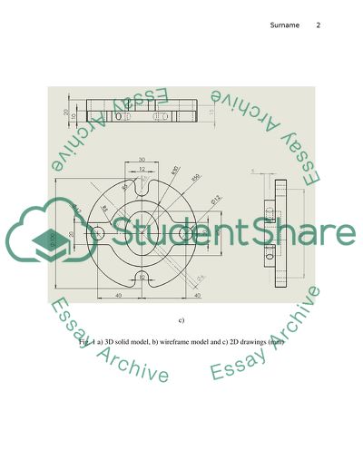
CAD Instructions Task Assume that you are working for a company, and only you know how to create CAD models using Solid Works. You are tasked to create the solid model of the part shown in Fig. 1, its drawings and write an instruction document which will be used to train engineers who have no previous CAD modelling and Solid Works experience. To create the instruction document you must include the following sections: a b) c) Fig. 1 a) 3D solid model, b) wireframe model and c) 2D drawings (mm) 1. Introduction to Solid Works 3D CAD solid models are the basic means of communicating design views and raising the new products and systems. In the 3D parametric modeling, facilitation of visual thoughts and the designing processes that represents the traditional forms of reading, writing and arithmetic. This stimulates the learners to make use of their imaginations and the whole problem solving skills that could help them become more literate technologically. Throughout the world, modeling system is part of the modern technology in education (Madsen, David A. And David P. Madsen, 11). . These new reforms are movements that seek improvement of critical thinking and multidimensional problem-solving skills. While technology prepares and inspires an increasing number of students, it has enabled some to be engineers and technologists of tomorrow. The hastened designs save time and costs in the development that boost productivity in the 3D solid modeling capabilities in solidworks and 3D designing software. The 3D solid modeling is one of the critical aspects of the modern products in development. Therefore, it provides the basis for crafting, simulation and developing many parts and assembly across the broad range of industries and the resulting products. In 3D solid modeling, Solidworks speeds up the formation of other complex parts and large assembling of different pieces. While creating the 3D solid models of different designs and not of 2D drawings it speeds up the designing development and improving visualization as well as communication. Creating the 3D solid models tend to eliminate other designs and interfere with some issues in some that are already created. This means that it helps in checking design functionality and take part in the performance that occur without the physical prototypes (Madsen, David A. and David P. Madsen, 75). . Similarly, it provides automatic manufacture of the 3D solid models that require programming using the CNC machines and rapid prototyping equipment. Solidworks comes up with automatic drawing updates that do not need to worry about modifications. The 2D drawing views become automatic that is created from the connection and the 3D solid model. The 3D solid model is modified and becomes the 2D drawing views that are automatically updated (Madsen, David A. and David P. Madsen, 30). . Solidworks 3D solid modeling features should enable one to create the 3D solid models of any part and in assembling large and complex parts. For this reason, keeping all the 3D models and 2D drawings that other designs and manufacturing documents that synchronize the automatic tracks updates. While creating quick variations and designs controlling the key design parameters should be directly edited by the model by simply clicking and dragging the model geometrically. Therefore, generating the surfacing of the 3D geometry is more complex organic and stylized shapes. As a result, the 3D model analyses the solid mass properties and volume, mass, density, and moments of inertia. 2. Key tools and techniques needed for modelling Surfaces and solids are the basic calculations that describe the geometry that forms that the 3D models created. There are three ways that one could define the 3D geometry, this includes solids, surfaces and wireframes. Wireframes play not much roles in the CAD, the straightest way to value the difference between surface and solids modelling is to consider solids modelling and surface modelling (Madsen, David A. and David P. Madsen, 22). . 3. Steps needed to create the model, demonstrated using edited screenshots Solidworks 3D CAD software gives designers simpler ways that rapidly create and change the 3D model geometry used in direct modelling. While creating the model the geometry is moved, and the speeding up design occurs. This saves time and develops costs, and increasing productivity. Additionally, the solid part model mainly consists of a group of features. These features are added one at a time, until the model is completed. In engineering, the solid models are built mostly with sketcher-based features, and 2-D sketches that are put together along to come up with 3-D. These mostly occur as cuts and extrusions. Designing work on such mechanisms usually occur in the context of whole products by using the assembly modelling methods. The assembly model includes locating different individual part models involved in the products. The other type of modelling procedure is surfacing. As such, the freeform surface modelling. This occurs in that the surfaces are defined, trimmed and merged, and filled to making solid (Madsen, David A. and David P. Madsen, 48). . As shown in the diagram, the surface is usually defined with datum curves that are in space and in a variety of complex commands. Therefore, Surfacing becomes more difficult and better application to some of the manufacturing techniques such as the injection moulding. Ultimately, the Solid models for injections moulded parts usually have both surfacing and sketcher based features. 4. Steps needed to create 2D drawings and dimensioning, demonstrated using edited screenshots. The 2D sketch is turned into 3D solids that is usually occur in an extrusion and it revolves in a certain process. This is noted as sketches that could be turned into the solid features that takes the same sweep or loft processes. Additionally, extrusions pull the sketches in the normal sketch plane as it revolve in certain features that allow the rotation of the sketches in an exact axis. Therefore, Sweeping allows the moves in the sketches along the path that is made up of a straight or a curved geometry. In the process, lofting always use multiple sketches in the process of transition from a certain shape to another. In addition, the sketch geometry is created through the capturing constraints that is used in sketching the dimensions fully while defining the geometry of the required shapes. While the sketches do not need to have the fully defined creation of features that are normally better in avoiding the possible later model distortion. Therefore, the fully defined sketch is black and it is in a desired state, as it is underdefined and sketched in blue on the other hand, the overdefined sketch is usually red(Madsen, David A. and David P. Madsen, 36). . Task 2 A company plans to manufacture the box shown in Fig. 2, only the pictures and one dimension are available. The length of the box is 135.7mm, and it is rounded to one decimal place (units’ mm). You are asked to create the CAD model and 2D drawings of the box. You must estimate the rest of dimensions and ensure that your CAD model is similar to the box shown in Fig. 2. You must present your 3D CAD model of the box, and 2D drawings with appropriate annotations in your assignment report. While creating the 3D CAD model, one is provided with an entity such as a rectangle with a thickness that is given solid sides in the given direction of the extrusion. In the figures on the right, the two boxes have been shaded using the Shade command, SHADE from the keyboard, ViewShadeOptions from the pull-down. Using SHADE for the description of the Shade command options, the box on the right is a rectangle with curves which has been given a thickness. As seen, the 3D Face has been put together so that at the top of the box and it was left therefore giving the resulting effect of a solid surface when shaded. When using the Shade command, get back to the wire line drawing. At last, the AutoCAD should not allow one to pick points on the shaded drawing. In other complicated shapes one is needed to use a number of 3D Faces to fill the surfaces. In the extruded circles, using the complexity of faces the surfaces, there are ways of hiding the joined lines between the faces. In the first point all the edges are made invisible. If one is careful one can easily fill the complicated surface that the 3D Faces that simply appear like a single continuous surface while avoiding curves. When one wants to create complex surface that becomes better using the EXTRUDE command and therefore creating solid extrusions that already have top and bottom surfaces. Using the associative links, there are different parts and assemblies that allows the drawings within the shortest time possible in the market. The greatest productivity is of lower costs reducing the design and errors in the visualization in the virtual testing that is prior to the manufacturing. Solidworks is the software that allows one to speed up in the designing process and whilst that ends up reducing the duration and development costs that are increased in the productivity of the Solidworks that becomes exemplary in the art of Solidworks 3D design software. In the 3D solid modelling the evolving and most crucial aspect of the resulting products is the development of the founded designing procedures that has allowed the emergency of simulation as well as the manufacturing factor in any part of the assembling process in the wider range of the industrial products and the necessary applications (Madsen, David A. and David P. Madsen, 57). a) b) c) d) Fig. 2 Four views of the box Work Cited Madsen, David A, and David P. Madsen. Engineering Drawing & Design. Clifton Park, NY: Delmar, Cengage Learning, 2012. Print. Read More
Tags
Cite this document
  • APA
  • MLA
  • CHICAGO
(3D CAD Solid Models Assignment Example | Topics and Well Written Essays - 1500 words, n.d.)
3D CAD Solid Models Assignment Example | Topics and Well Written Essays - 1500 words. https://studentshare.org/information-technology/1853486-cad
(3D CAD Solid Models Assignment Example | Topics and Well Written Essays - 1500 Words)
3D CAD Solid Models Assignment Example | Topics and Well Written Essays - 1500 Words. https://studentshare.org/information-technology/1853486-cad.
“3D CAD Solid Models Assignment Example | Topics and Well Written Essays - 1500 Words”. https://studentshare.org/information-technology/1853486-cad.
  • Cited: 0 times

CHECK THESE SAMPLES OF 3D CAD Solid Models

Business Opportunities of 3D TV Without Glasses

3d TV without Glasses” A Business Plan Introduction The television industry and related media have goon through an immense boom in the last century.... However, the next ‘big thing' in the television market in 3d technology which literally brings the characters on screen into the living rooms of the users.... Though existing since the mid 1900s, the 3d technology had always been relegated to the realm of ‘unnecessary fads'.... Attempts to popularize the technology were made in the 80s but due to ineffective marketing, devices which did not perform as well as had been hyped and an extremely extravagant pricing well above the price point of the average consumer, the trend of 3d did not catch on....
9 Pages (2250 words) Essay

The Ising Model

This essay is aimed at explaining what the Ising Model.... Also, the author explains the background and historical significance of the model and what are its contributions to modern physics.... And also the author demonstrates the aim of using this model.... hellip; The Ising Model, which has been named after the German physicist E....
7 Pages (1750 words) Essay

Technology discuss about ( IGES) & (X3D)

IGES is a commonly used for data interchange of 2D and 3d cad model.... t precisely represent CAD models and geometric representations through its entities of points, lines, arcs, splines, NURBS surfaces and solid elements.... The test designed the Altan Machine Company's Quick coups and Fork using the solid works, then it was presented in both 3D XML and IGES format.... It is also used to illustrate simple figures of cad or "drawing" applications....
2 Pages (500 words) Essay

A business innovation which has brought to life a product (good or service)

The 3D printing innovation applies in the commercial sector where manufacturers use it to produce early concept models and product prototypes for business purposes.... The 3D printing case is relevant in the context of digital economies since it allows for the production of early concept models and product prototypes.... Also known as additive manufacturing, 3D printing is business and technological innovation that encompasses the process of making a three-dimensional solid product of any shape using a digital model....
5 Pages (1250 words) Essay

Introduction to the Universe

The differences in the sounds made can be attributed to the nature, structure and properties of the materials beneath the skin.... In the forehead, there is a thin layer of flesh… Thus, the soft material of the cheek produces a different sound from that of the harder forehead when the two are flicked with a finger....
3 Pages (750 words) Essay

The Popularity of Financial Ratios in Multivariate Modeling

In this report, “The Popularity of Financial Ratios in Multivariate Modeling” the author will advise NENE limited on various projects they are hoping to take up.... Different appraisal methods will be used including NPV, ARR, Cash flow and Payback period methods.... hellip; The author explains that Internal Rate of Return is the method that gives the investors an easy way of estimating the quantity or rate of return that an investment is expected to offer....
16 Pages (4000 words) Essay

IC Insights - Dataset Analysis

Generally, contents of a single data matrix are recorded in a dataset to give the user a comprehensive view of a particular topic (Mirer, 2014, n.... ).... A dataset is prepared using relevant portions of a database.... In a dataset,… Each value of the variable in a dataset is called datum (Johnson, 2000, p....
12 Pages (3000 words) Essay

Global operation and supply chain

The models are;Single-period Inventory modelsThis is a model used to identify the amount of inventory to purchase given a single opportunity.... ulti-period models comparison.... Inventory (stock) management refers to the process of effectively and efficiently overseeing the constant flow of units in and out of an existing inventory....
2 Pages (500 words) Essay
sponsored ads
We use cookies to create the best experience for you. Keep on browsing if you are OK with that, or find out how to manage cookies.
Contact Us