StudentShare
Contact Us
Sign In / Sign Up for FREE
Search
Go to advanced search...
Free

Inductive Reactance - Assignment Example

Cite this document
Summary
The paper "Inductive Reactance" calculates inductive reactance XL = 2 fL given f= 100 Hz, L=105.3mH=105.3 x 10⁻³ H = 2 x 100 x 105.3 x 10-3 = 66.162 Ω. (impedance)2= (resistance)2 + (reactance)2 = (45)2 + (66.162)2 = 6402.41, Impedance = 6402.41= 80 Ω…
Download full paper File format: .doc, available for editing
GRAB THE BEST PAPER93.8% of users find it useful
Inductive Reactance
Read Text Preview

Extract of sample "Inductive Reactance"

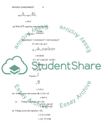
With 25 F capacitor connected in series,
Current =
(Impedance)2 = (resistance)2 + (net reactance)2
Z2 = R2 + (XL-XC)2
XC = =
= 63.66 Ω
Z2 = 452 + (66.162 - 63.66)2
= 2027.502
Z = 45 Ω
Current =
=
= 2.22 A
(h) Voltage across the resistor IR = 2.22 x 45
= 99.9 V
(i) Voltage across the coil = IXL
= 2.22 x 66.162
= 146. 87 VAR
(j) Voltage across the capacitor = IXC
= 2.22 x 63.66
= 141. 33 VAR

(k) Phase angle between supply voltage and current is given by
tan-1( ) = tan-1( )
= 3.18°

Task 2;
(a) Efficiency =
Apparent input power =
=
= 9.33 KID
The apparent current is drawn by the motor =
=
= 40.56 A
(b) With the power factor improved to 0.925,
Load KVA =
= 7.31 KVA
Supply current =
=
= 31.78 A
(c) Capacitor connection involves the parallel connection of the capacitive reactance and motor impedance.
(Resultant current)2= (sum of active components of current)2 + (sum of reactive components of current)2
31.782 = (IC cos(90) + IM cos )2 + (IC sin(90) - IM sin )2
= (40.56 x 0.725)2 + (IC - (40.56 x 0.689))2
1009.97 = 864.713 + (IC - 27.94)2
(IC - 27.94)2= 145.257
IC - 27.94 = 12.05
IC = 27.94 + 12.05 = 39.99 A

(d) With the power factor at 0.725,
Load KVAR= KVA x sin
= 9.33 x sin (43.53)
= 6.43 KVAR
With the power factor improved to 0.925,
New KVAR = New KVA x sin (22.33)
= 7.31 x sin (43.53)
= 2.78 KVAR
Therefore leading KVAR required to be supplied by the capacitor
= 6.43 - 2.78
= 3.65 KVAR
But leading KVAR= IXC
XC =
=
= 91.27 Ω
XC =
C= =
= 34.87 F
(e) KVAR rating of the capacitor = Load KVAR- New KVAR
= 6.77- 2.78
= 3.65 KVAR leading

Task 3;
(a) The p-n junction diode is a two-terminal semiconductor electronic device that conducts current in one direction only. It allows low resistance to the flow of current in one direction and very high resistance in the reverse direction. A semiconductor material, usually silicon, germanium, or gallium arsenide is added with impurities or doped to form an n-type region with negative charge carries on one side and a p-type region with positive charge carries on another side. The two are attached together resulting in a depletion region with no charge carriers between them and the terminals are connected at the ends of the two regions. The resulting crystal allows the flow of electrons across the junction from the n-type region to the p-type region (forward bias) but not the reverse (reverse bias), thus blocking current flow in one direction.

(b)
(i) In the purely resistive form of circuit, the current is always in phase with the voltage.
For the fundamental wave, R1= 25 Ω. For the second harmonic, R2=2 x 25 = 50 Ω. For the third harmonic, R3= 3 x 25= 75

Current iR = = (1000 t + ) + (2000 t - ) + (3000 t + )
iR = 8 (1000 t + ) + 3 (2000 t - ) + (3000 t + ) A
(ii) In a purely inductive circuit, the current is lags behind the voltage by rads.
For the fundamental wave, X1= 2 x 500 x 0.025 Ω = 78.54 Ω. For the second harmonic, R2=2 x 78.54 = 157.1 Ω. For the third harmonic, R3= 3 x 78.54= 235.6 Ω

Current iL = = (1000 t + - ) + (2000 t - - ) + (3000 t + - )
iL = 2.55 (1000 t - ) + 0.955 (2000 t - ) + 0.32 (3000 t + ) A
(iii) In a purely capacitive circuit, the current is leads the voltage by rads.

For the fundamental wave, X1= Ω = 12.73 Ω. For the second harmonic, R2= 2 x 12.73= 25.46 Ω. For the third harmonic, R3= 3 x 12.73= 38.2 Ω
Current iC = = (1000 t + + ) + (2000 t - + ) + (3000 t + + )
iC = 15.71 (1000 t - ) + 5.89 (2000 t + ) + (3000 t + ) A

Task 4;
(a) Given the turn ratio 25: 1, secondary voltage= 5000 x
= 200 V
Full load secondary rating = VSIS = 10 kVA
IS =
= 50 A

(b) Given secondary voltage= 200 V,
minimum load resistance, RL = = = 4 

(c) = for which primary current = I1 = x I2 = = 2 A

(d) Secondary impedance referred to the primary = ZS’ = ZS x ( )2
Impedance seen at the input = 4 x 252= 2500 

(e) Power dissipated across load resistance = I2R = 502 x 4
= 10 kW Read More
Tags
Cite this document
  • APA
  • MLA
  • CHICAGO
(“Ac Assignment Example | Topics and Well Written Essays - 1000 words”, n.d.)
Ac Assignment Example | Topics and Well Written Essays - 1000 words. Retrieved from https://studentshare.org/physics/1694718-ac
(Ac Assignment Example | Topics and Well Written Essays - 1000 Words)
Ac Assignment Example | Topics and Well Written Essays - 1000 Words. https://studentshare.org/physics/1694718-ac.
“Ac Assignment Example | Topics and Well Written Essays - 1000 Words”, n.d. https://studentshare.org/physics/1694718-ac.
  • Cited: 0 times

CHECK THESE SAMPLES OF Inductive Reactance

Reactive Power compensation

The addition cancels the effects resulting from a load's Inductive Reactance.... Notably, only capacitive reactance can cancel the Inductive Reactance and hence a parallel capacitor is added to the provided circuit to act as the extra load.... As a result of the impact resulting from the two reactance acting in opposite directions, and parallel to each other, the circuit's total impedance becomes equivalent to the entire resistance.... Given that the identified capacitor will act in a direction parallel to the source, the following formula is applied in calculation and it begins with identification of voltage and reactance: But And hence, The simulation is done using a rounded of capacitor value of 29, yielding the following results, True power = 447....
7 Pages (1750 words) Essay

Engineering Science

In a series LC circuit, resonance occurs when the Inductive Reactance (XL) is equal to the Capacitive Reactance (XC).... The paper "Engineering Science" tells us about resonant frequency.... Using the formula, the calculated value of the resonant frequency is 1/ 6.... 83 * 10-3 = 159....
7 Pages (1750 words) Research Paper

A Major Application of Series Resonance

The author points out that it's achieved when an RLC circuit is arranged in series and at a point when the magnitude of Inductive Reactance and capacitive reactance is equal.... The changes in both the capacitive and Inductive Reactance were observed and tabulated.... It was noted that an increase in frequency caused an increase in Inductive Reactance, while a decrease in capacitive reactance.... eries resonance occurs in a series RLC circuit when the capacitive magnitude is equal to the magnitude of Inductive Reactance....
7 Pages (1750 words) Lab Report

Application of Series Resonance

The author points out that it's achieved when an RLC circuit is arranged in series and at a point when the magnitude of Inductive Reactance and capacitive reactance is equal.... The changes in both the capacitive and Inductive Reactance were observed and tabulated.... It was noted that an increase in frequency caused an increase in Inductive Reactance while a decrease in capacitive reactance.... eries resonance occurs in a series RLC circuit when the capacitive magnitude is equal to the magnitude of Inductive Reactance....
5 Pages (1250 words) Lab Report

Computer Programming Techniques

The set of outputs that the program is designed to produce include; the Inductive Reactance, capacitive reactance, complex impedance, Z amplitude, Z phase, and current.... For the manual purpose, the complex reactance, Z Amplitude, and Z phase are highly dependent on the results in Inductive Reactance and capacitive reactance.... he variables used in programming include the Inductive Reactance, capacitive, complex impedance....
6 Pages (1500 words) Assignment

Course Skills and Concepts

The voltage opposed to changing generating another form known as reactance, which is precisely opposite to the kind inductors exhibit.... This paper ''Course Skills and Concepts'' tells that According to Newton's law, a force is necessary to change the state rest along a straight line....
6 Pages (1500 words) Coursework

A Tuner Circuit Analysis

In this analogy, the resonance in the circuit will only occur when the value of both the capacitive and Inductive Reactance are equal to each other.... When an inductor produces Inductive Reactance in an alternating current circuit and the result is lagging, an increase in the frequency will result in an increase in the inductive resistance of the circuit (Hassan, 2002).... The opposition that is produced by the inductor to the alternating current is referred to as the reactance....
6 Pages (1500 words) Report
sponsored ads
We use cookies to create the best experience for you. Keep on browsing if you are OK with that, or find out how to manage cookies.
Contact Us