StudentShare
Contact Us
Sign In / Sign Up for FREE
Search
Go to advanced search...
Free

Parameters and Characteristics of Single-phase Induction Generator - Term Paper Example

Cite this document
Summary
According to research findings of the paper “Parameters and Characteristics of Single-phase Induction Generator”, single-phase inductor generators operate by mechanically turning the rotor of the generators at faster speeds than the synchronous speed in order to produce torque through electromagnetic induction…
Download full paper File format: .doc, available for editing
GRAB THE BEST PAPER95.8% of users find it useful
Parameters and Characteristics of Single-phase Induction Generator
Read Text Preview

Extract of sample "Parameters and Characteristics of Single-phase Induction Generator"

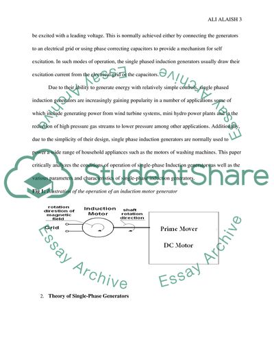
Parameters and Characteristics of Single-phase Induction Generator Table Contents Parameters and Characteristics of Single-phase Induction Generator 1. Introduction Single-Phase Induction Generators are simple AC motors that employ the principles of induction to derive their power (asynchronous power generation). The use of induction motors as generators is currently one of the most cost effective ways of generating electricity from wind turbine systems and other common applications. This is particularly achieved by mechanically turning the rotor of the generators at faster speeds than the synchronous speed in order to produce a torque through electromagnetic induction. For example, rather than consuming energy, a single phased motor can effectively be used to generate power by driving it at speeds over its rated speed (Murthy 8). The working principle of single phase induction generators is similar to that of the three phase induction generators. For example, all induction generators generally work on induction principle based on Faradays law of conduction that states that when a conductor moves in a magnetic field, an electric voltage that can potentially set up a current is induced. However, unlike three phase induction generators, single-phase induction generators are not self starting and, therefore, require excitation in order to start. Single-phase induction generator must always be excited with a leading voltage. This is normally achieved either by connecting the generators to an electrical grid or using phase correcting capacitors to provide a mechanism for self excitation. In such modes of operation, the single phased induction generators usually draw their excitation current from the electrical grid or the capacitors. Due to their ability to generate energy with relatively simple controls, single phased induction generators are increasingly gaining popularity in a number of applications some of which include generating power from wind turbine systems, mini hydro power plants and in the reduction of high pressure gas streams to lower pressure among other applications. Additionally, due to the simplicity of their design, single phase induction generators are normally used to power a wide range of household appliances such as the motors of washing machines. This paper critically analyzes the conditions of operation of single-phase Induction generators as well as the various parameters and characteristics of single-phase induction generators. Fig 1: Illustration of the operation of an induction motor generator 2. Theory of Single-Phase Generators There are two major theories that have been put forward to explain the principles of operation of single-phase induction generators namely; cross field theory and double-revolving theory. For example, cross field theory attempts to explain the operational principles of single phase induction motors and generators based on the assumption that immediately after a rotor, a speed emf E is normally induced in the generator’s rotor conductors while they cut the stator flux Fs. (Hubert 44). The theory suggests that this voltage normally increased with the increasing speed of the rotors thereby causing the current rotor IR to flow through rotor bars that are facing the stator poles as shown in the figure above. Additionally, according to the theory, the current produced at rotor bars often results in an influx which then acts at right angle to the stator flux Fs. In this regard, it is the combined action of rotor flux FR and Fs that works together to produce a rotating magnetic field. Fig 2: Induction of Electric Current in the Rotor Bars due to Rotation Another important theory that seeks to explain the operational conditions and principles of single-phase induction generators is known as double-revolving theory (Hubert 47). According to this theory, the single-phase power provided to the single-phase winding often produces a pulsating field that can effectively be resolved into two major components that are oppositely rotating but with equal magnitude. Fig 2: Double revolving theory- Pulsating Field Resolved Into Two Oppositely Rotating Fields 2.1. Theory of single phase induction generator as motor Single phase induction generator short circuit as motor no load test particularly reveals the potential impacts of core loss and mechanical power loss on the efficiency of single phase induction generators. For example, the operation of Single phase induction generator short circuit as motor no load can effectively be used as a test to determine the efficiency of induction motors by loss estimation under no load conditions using a graph of mechanical power loss (Pm) and Core loss (Pfe). Generally, power losses in induction motors such as core losses, copper losses and mechanical losses often impact on the efficiency of the motors. The cooper loss on the windings (I2R) often occurs when the current (I) pass through a conductor winging (usually copper). Copper losses (R*I1^2) include all the resistive losses that occurs in the stator windings as well as in the rotor windings. Although copper losses are the main component in induction motors, the other loss components can not be neglected. On the other hand, the core losses also referred to as iron losses are a representative of all the magnetic losses in the induction motor attributed to the varying flux in the magnetic material of the motor. Core losses are primarily attributed to hysteresis effect and the eddy current losses and may also affect the efficiency of the motor. Lastly, the mechanical loss (∆Pm) occurs due to either bearing friction or ventilation loss. Bearing friction loss is often caused by machining inaccuracies while ventilation loss is primarily related to the revolting speed, motor structure and air gap. For example, the alternating magnetic filed often causes fluctuating magnetic forces between the secondary and primary windings. The resultant vibrations may consumer some small amounts of power. The higher the speed of the induction motor, the higher the windage or friction losses. Generally, the machine works by the same mechanism of operation of three phase induction except that its stator is wound on a single motor. Capacitors are normally used to provide the needed excitation to the generator in order to magnetize its rotor. According to many experts, it is the magnetized rotor moving past the windings that generate voltage. Alternating current passing through the stator winding then produces induced current in the rotor bars based on Faradays law of electromagnetic induction. In this regard, the voltage and frequency produced by the motor is dependent on a number of factors some of which include the number of turns in the windings, the speed of the rotor as well as the load applied to the generator. When the induction generator is started, little mechanical and core losses occurs and this is often indicated by the auxiliary resistance when running the induction motor. Additionally, the currents are higher during this phase and this is particularly attributed to the short circuit state as well coupled with the lower parallel resistance. However, as the induction motor continue to run, the core losses normally rises up and thereby causing potential damage to the induction generator. In summary, core losses will increase during the operation of an induction motor with increasing power and voltage. Generally, the increasing core losses are particularly attributed to the short circuit conditions. On the other hand, mechanical losses are primarily attributed to machining inaccuracies are normally constant throughout the operation of the motor. The losses are normally manifested in the induction motor as a reduction in the toque. Fig. 1: Characteristic curve of Mechanical Power Loss Pm & Core Loss (pfe) Power Pin Core loss Mechanical loss Un2 Voltage 2.2. Theory of single phase induction generator no Load The no load test on induction generator primarily gives information regarding the exciting current and no load losses. Just like in a three phase induction generator, no load test can also be effectively performed on a single induction motor in order to provide the circuit parameters of single phase induction generators. The test is particularly performed to determine the no load current I0, no-load power factor cos Ø0, friction losses and windage, no core loss, no load input as well as no load resistance of the system. This can be achieved by using different applied voltage values below and above the rated voltage while the motor is running without load. According to Hubert (22), motor no load test is conducted on single phase induction generators by simply rotating the motor without a load. The input current, power and voltage are then measured by connecting voltmeter, ammeter and wattmeter on the circuit. The readings are generally denoted as Vo , Io and W o  respectively.   Wo = Vo Io cosΦ When the induction motor is allowed to freely run at no load, the forward slip normally approaches zero while the backward slip approach2 (s s f =,s s b = 2 ). For example, when on no load, the speed of the motor is normally almost equal to its synchronous speed hence the slip is usually assumed to be zero. In this regard, r2/s becomes ∞ and works as open circuit in the corresponding circuit. For the forward rotor circuit, the branch r2/s + j x2 is eliminated while r2/ (2 - s) tends to r2/2 for the backward rotor circuit. The secondary forward impedance then becomes very large with regard to the magnetizing branch while the secondary backward impedance becomes smaller in relation to the magnetizing branch. Theoretically, a no load voltage often increased with the parallel excitation. A characteristic curve of induced voltage with increasing speed with a given constant for a fixed capacitor usually takes a linear shape. This is particularly attributed to the fact that as the induced voltage that is generated by the use of auxiliary systems rises up linearly, the no load state for increased speed also induces higher voltage and the induced voltage increases with lower capacitors (Herman 34). As speed continues to increase, the voltage build up begins due the mutual inductance variation until it reaches a steady state voltage. This consequently leads to a linear function between the induction voltage used in the auxiliary system and the capacity of the capacitor. Fig 2: A characteristic curve of induced voltage with increasing speed with a given constant for a fixed capacitor Voltage Constant capacitor n Speed 2.3. Theory of Single Phase induction Generator with Load, Speed and Capacitor Constant Single phase induction generator with load, speed and capacitor constant tests are carried out to help determine the load characteristics of an induction motor engine. When the load, speed and the capacitor is constant, the torque normally increases with the increase in current and can be calculated by considering the saturation and neglecting the iron losses. According to Boldea and Nasar (45), this confirms the linear relationship between torque and speed based on the assumed speed-torque characteristics. With regard to induction voltage versus current for increasing the load, the voltage decreases when the current increases and rises up when the current reduces. Generally, when the load increases, the current also rises up. This mechanism is particularly explained by the fact that the inductors always oppose any changes in the current and the voltage often decreases as the current rises up. For example, based on Lenz’s law, the induced voltage opposes any change in the current. In this regard, the amount of induced voltage depends on how rapidly the current decreases with the increasing load. The induced voltage therefore increases with the rapidity of the decrease (Murthy, Singh and Sandeep 117). As the current decreases with the increasing load, the voltage polarity normally orients itself so as to maintain the current at its former magnitude. For example, Power=Voltage (V) x Current (I) and therefore any increase in the current will result in a decrease in the voltage. In such scenarios, the inductors often act as the source with the positive side of the induced voltage being on the end in which the electrons are entering while the negative remains at the exit end of the electrons (Boldea and Nasar 58). It is however, worth noting that voltage collapse often occurs due to an increasing load which causes dropping voltage thereby reducing the reactive power from the capacitor or line charging. Finally, it can be argued that the linear characteristics between the induced voltage and the currents may be attributed to the fact that the leakage inductances are not normally influenced by saturation. At some point, the linear relationship between the current and the voltage will be expected to breakdown due to excess current as shown in the curve below. Fig 3: Characteristic curve of induce voltage Versus current for increasing the load Voltage I max Current On the other hand, with regard to the relationship between power and current, an increase in power will result in an increase in the current. For example, an increase in the reactive power normally lowers voltage thereby forcing the current to increase in order to help maintain the supplied power. However, the increasing current with power will only continue up to a particular level when further increasing currents may cause overloading and cascading failures leading to problems such as excessive heading and shortening of the life of the motor. This is particularly true when the increasing current exceeds the current name plating rating of a particular motor. Fig 4: Characteristic curve of power Versus current Power I max Current 2.4. Theory of Single Phase induction Generator with Load and Change Capacitor, Speed and Voltage Constant With regard, to the operation of the operation of a single phase induction (speed and capacitor constant), when both the speed and capacitor are constant, the induced voltage increases with the increasing current until the current reaches its maximum limit at I max. After this, the induced voltage begins to reduce with further increase in the current. According to Faraday’s electromagnetic law of induction voltages normally increase with the current until the maximum limit of the current is reached in the induction motor (Björnstedt , Sulla and Samuelsson 1234). Induced voltage Current According to Björnstedt , Sulla and Samuelsson (1238), under constant voltage, the starting current will gradually decrease with the increasing speed of the motor until the motor reaches between 70% and 80% of its full speed. After this, the current normally begin to fall significantly. Although the characteristic graph curve for speed and current when the voltage is constant considerably varies depending on the designs, the normal trend is that for an increasing current until the induction motor has almost reached its full speed. Theoretically, this can be explained that the fact that an induction motor normally achieves its optimum operating efficiency at ¾ of the speed (Björnstedt , Sulla and Samuelsson 1234). However, the motor begins to operate at low slip once it reaches its maximum speed. Fig 5: Characteristic curve of speed with current (voltage constant) Speed Current 3. Construction and Design of a Single-Phase Induction Generator Single-phase induction motors are nonsymmetrical two-phase motors with a main winding and an auxiliary winding. The construction of a single-phase induction generator requires a number of essential components some of which include a rotor, a stator, an air gap and auxiliaries. Since a single phase induction generator is a rotating machine, it should have both a stationary and a rotary part. In this regard, the stationary part is the induction generator is the stator while the rotating component is knows as a rotor. The construction of a stator of a single phase inductor generator involved winding a cooper wire in the slots cut in the stator. On the other hand, rotors can be constructed using two methods namely wound rotor and squirrel cage rotor. To reduce eddy current losses in the induction generator, the rotor core must be properly laminated. In case of a wound rotor, the winding is similar to that of the stator but with lesser number of turns and slots. squirrel cage rotor should be constructed using solid bars made from conducting materials that are placed in the rotor slots. The bars are then permanently short circuited at both of their ends. There are two major designs of a single-phase induction generator: revolving armature and revolving field. Revolving armature is a design type in which the magnetic field remains on the stator with the armature mounted on a rotor. The set up has a rectangular loop designed in a way to let it cut the magnetic field while rotating consequently producing electric current. The brushes and slip rings turn helpful in conducting the produced current out of the generation. The other category of design is revolving field which is designed in such a manner that the magnetic field section lies on the rotor while the armature part lies on the stator. The remaining section of this paper provides a detailed description of the characteristics and parameters associated with the single armature design. In this design type, the armature goes through a single revolution generating a cycle of single-phase alternating current. For generation of an a.c output, the armature goes through a rotation at a constant speed with the total number of rotations in every second matching the targeted frequency of the given a.c output. A.c output and armature rotation bear a lot of relationship. Varied number of lines of force will be cut at steady speed of motion because of the armature’s circular motion. The armature’s rectangular arm never cuts any line of force at zero degrees resulting into an output of zero voltage. While the armature arm is rotated at a constant stable speed towards position 90°, an increasing number of lines will be cut. An armature at the 90 position makes the lines of force to be cut most giving the largest amount of current in a single direction. While it moves towards position 180°, there will be a decreasing number of the lines of force cut, this gradually lowers the voltage till it turns to zero when the armature is at 180°. This voltage begins increasing again while the armature tends to the opposite pole situated at position 270°. As the armature nears this position, the generated current is on an opposite direction producing maximum voltage amounts on the opposite side. The revolving armature allows for addition of extra poles to make a single rotation produce multiple cycles of AC output. For instance, introducing four poles would one part of the armature to interact with the south pole and the other with the north pole with the difference that it will be possible completing one a.c output cycle after rotating the armature through 180-degree thus increasing the frequency of the generator’s output. Also, the design allows for modification of the armature’s shape with the aim of increasing the output voltage. 4. Conditions of Operation of Single-Phase Induction Generators The operational principles of Single-Phase induction generators are simply based on the generation of electrical power by turning the rotors faster than the synchronous speed. This is achieved using a prime mover such as wind turbines or engines connected to the induction motor and designed to drive the rotor at speeds above synchronous speeds (negative slip). According to Leicht and Makowski(48), the rotor of the generator is placed within the rotating magnetic field and is then spun by an external source of mechanical energy such as wind turbines so that it can rotate at higher speeds that the magnetic field. In this regard, the rotating shaft drags the magnetic field forward thereby generating electric flow into the coils of the generator. Generally, increasing the rotation per minute of the rotor than the speed of the rotating magnetic field from the stator normally facilitates the induction of strong electric currents in the rotor. The difference between the operating speed of the rotor and the synchronous speed of the magnetic field is known as slip. Slip if often expressed as a ratio or percentage of the synchronous speed of the single phase induction motor. For example, an induction motor operating at speeds of 1450 rpm but has a synchronous speed of 1500rpm is operating at a slip of +3.3%. The speeds of single phase asynchronous generators often vary with the turning force depending on the torque applied to it. This is an important advantage because it ensures that the generator is able to remain in operation at varying speeds such as during varying wind conditions when used with wind turbines or during water flow variations when used in micro-hydro generation plants. During normal induction generator operations, stator flux rotation is usually faster than the rotation of the rotor. This may create a rotor flux with a magnetic polarity that is opposite to the stator thereby inducing rotor at the slip frequency. However, since, the active current produced in the stator normally sends the power back to the electrical grid. 5. Parameters and Characteristics of Single-phase Induction Generators Single phase Induction generators have a number of parameters related to their design and functionality. Generally, the motors normally use turbines to rotate their motor windings and cause a magnetic flux by exciting the windings connected to an external power source. The end of the stator is then connected to the required load and the induction generator operates only when there is a slip. According to many experts, single-phase Induction Generators employ the inherent characteristics of induction AC motors to convert mechanical energy into electric power. When connected to electric grid, an asynchronous generator often operates both as a motor as well as a generator. Speed deviation below or above the synchronous speed also known as asynchronous operation often determines whether the energy is supplied or absorbed. Additionally, the frequency is normally governed by the electric grid particularly through its large capacity. Equivalent circuit of a self excited self excited single phase induction generator From the above equivalent circuit, the main auxiliary and winding impedances can be as follows: ZImL = Rsm/F + jXSm + RL/F + JxL - jXCSm/F2…………………..1 Z 2al = Rsa/2Fa2 + jXsa/2a2 - Jxcca/2F2a2 - Z1Ml/2………………..2 Z+ = (jXmm (Rmm/(F-U) + jXmm )) /( (Rm / (F-U) + j(xmm + Xmm)) Z- = ( jXmm ( (Rmm / (F + U ) + jXmm)) / (Rm / (F + U)+j(Xmm + Xm)) The above can however, be simplified through combining of parameters to give an equivalent circuit shown below: 1 / (ZImL+Z+) =( 1 / (ZImL + Z-)+1/ZIl)…………………..3 On the other hand, the value per unit frequency (F) as well as the main winding reactance can be chosen wisely with known magnetization curve from the measurements to help solve the unknown from equation 3 shown above. Generally, the main winding reactance(Xmm) is often a function of the magnetizing current Xmm(Imm). The computation can be further simplified through consideration of Z- as Z- = (Rrm/F + U) + jXm Assuming all parameters constant except Xmm , Z+ can be expressed as a subject of all other parameters and it is shown bellow. Z+ = (Zim +Z-) * ZL / (ZimL + Z- + ZL) - ZimL………………..4 On the other hand, Z+ = f (F) for the particular value of speed n, capacitors and load, can be calculated for the row values of F. The relationship is represented as follows: Z+ (F, Xmm ) =( jXmm (Rmm /(F + U) + jX sm)) / ( j(Xrm + Xcm) + (Rmm / ( F – U)))………5 The load current of the system can be calculated by summing the two currents Im = Im+ + Im- While the auxiliary current is determined as Is = j(Im+ -Im+) The output power is then calculated as POut = Im2*RL On the other hand, the rotor current given by the equation Ir+ = -Im +* jXmm / (Rrm / (F-U) + j(Xrm + Xmm)) The total input active power from the shaft is derived from the equation: Pinput 2I2r+*( Rrm*U) / (F-U) -2I2m- *RrmU / (F+U) 5.1. Torque (Te) Versus Speed (slip) With regard to the torque and speed characteristics of single phase generators, the double revolving field theory suggests that each of the revolving fields act independently on the rotor. On the other hand, the clockwise component produces the torque characteristic Tcw while counterclockwise produces the torque Tccw as shown below. An alternating current is produced in the rotor by the changing magnetic field. The rotor induces a magnetic field from the current. The magnetic field acts together with the stator’s magnetic field making the rotors turn. The rotor in induction motors consists of cylindrical arrangements of copper or aluminum conducting bars joined to two end rings at both ends of the bars. Single-phase induction motors have low power motors because the current is not fed directly to the rotor from the main supply. Less power reaches the rotor because the current is induced by the stators changing magnetic field. The rotating rotor field in a single-phase induction motor is irregular making the torque developed to be irregular. This wastes energy through vibration and sound. Addition of excess load on the motor normally results in a negative slip thereby causing power to flow from the grid or capacitors to the induction motor. On the other hand, when the mechanical energy such as wind turbines used to drive the rotor of the single-phase induction generators exceeds its synchronous speed, the flow of energy is normally reversed and the resultant positive slip enables the generator to supply electric energy to the grid. Due to their large operating speed range, single-phase induction generators, asynchronous generators machines such as single phase induction generators do not require costly synchronizing equipment during operation. As the speed is varying, the slip will be changing. To yield realistic result, the load resistance should be changed with the slip from the beginning. The function Xmm(Vg+) is presented in a table for different values . The function Xmm (F) is also presented in the table. The value of the Xmm is the checked from the table. Failure to find it from the given data means that the either the load impedance or the capacitors for a particular frequency and speed is not within the existence domain. This will call foe modification of load impedance or the capacitor to fit in the required domain. 5.2. Efficiency (η) Versus Speed Single phase induction generators can continue to produce power even if the speed of their rotors changes and this is a major advantage over the other forms of electricity generator. An external supply of electricity is therefore required to create a rotating magnetic filed and start operating such generators. For example, when voltage is supplied to the stators(stationary coils), a stator magnetic filed is created and the changing nature of this magnetic field due to rotor movement results in a magnetic flux leading to induced voltage. Once the system starts generating power, it can run on its own without stops as long as it has a source of mechanical energy that turns the rotors such as wind turbines. The output frequency of single-phase induction generators normally varies depending on the power level of the mechanical energy that is driving the rotor. Another important characteristic is that during its operation, the induction motors obtains its field from the grid or phase correcting capacitors. This is particularly because unlike three phase induction generators, single-phase induction generators are not self starting and, therefore, require excitation in order to start. In this regard, an electrical grid or phase correcting capacitors is primarily intended to provide a mechanism for self excitation for the generators. 6. Characteristics and Parameters Obtained from the Model The analysis of the model revealed a number of characteristics and parameters of single phase induction generators. One of the characteristics obtained from the model is that electrical power is only produced when the shaft of the induction generator is rotated at a faster rate than the synchronous frequency. For example, the prime mover of the system (DC motor ) must drive the rotor at higher speeds that the speed of the rotating magnetic field. Another important parameter or characteristic that was obtained from the model is that the increasing load can result in a drop of the voltage. In this regard, in order to maintain the desired level of terminal voltage, additional capacitance may be required as compensation to the increased voltage requirements due to 7. Potential Applications and Benefits of Single-phase Induction Generators With the increasing high energy costs, single phase induction generators currently offers one of the most cost effective ways to generate energy with very minimal maintenance of control systems. Additionally, due to their simplicity, single-phase induction generators are gaining popularity for wide range of household applications. Some of the major potential benefits of these generators include their low prices, simple construction, robustness, and low maintenance requirements. They do not need direct current sources and brushes. It makes them suitable as energy conversion devices for renewable energy sources. Renewable energy is currently being explored all over the world due to its reduced damage to nature (Herman 531). On the other hand, single-phase generators can also operate in standalone or grid interactive mode. They are connected directly to a grid that imposes its voltage and frequency. They supply the required reactive power. In standalone, mode self-excitation capacitors are required. They give the reactive power to the generator and the load. The rotation speed, load impedance and excitation capacitors values determine the generated voltage. Induction generators require an external supply of reactive power, which supplies the rotating magnetic flux wave. It makes is impossible for induction machines to serve as standalone generators. The use of capacitors connected to stator terminals enables induction machines to function as self-excited induction generators. The capacities supply required reactive power, making it possible for the generation of energy in remote areas. The self-excited induction system consists of the prime mover, the induction machine, the load, and the self-excitation capacitor bank. Self-excited induction generators have poor voltage and frequency control. The drawback makes them unreliable under variable load conditions as control of speed and voltage does not give reliable results. Changes in the load impedance directly influence machine excitation as both the induction machine and the load impedance share the reactive power of the excitation capacitors. It makes the generator voltage drop when the load impedance increases. Poor voltage controls results. The slip of induction generators, increase with increasing load. It results in load dependent frequency regardless of whether the prime mover speed remains constant. Mechanical prime movers can drive Standalone induction machines. The remaining magnetic field in the machines rotor induces an electromotive force in the stator windings at a frequency equivalent to the rotor speed. The Electromotive force is applied to the capacitors connected to the stator terminals and it causes a reactive current to flow in the stator windings. Magnetic saturation limits the stator voltage value within the machine. According to Herman (529), a self-excitation phenomenon enables induction machines to operate as generators in remote locations without grid supply. Nonlinearity of the magnetizing curves, value of self-excitation capacitance, speed, machine parameters, and terminal loads determine the magnitude of steady state voltage generated by the self-excited induction generator once the machines are excited and loaded (Brennen and Abbondanti 426). 8. Conclusion In conclusion, single-phase inductor generators operate by mechanically turning the rotor of the generators at faster speeds than the synchronous speed in order to produce a torque through electromagnetic induction. The operational principles of Single-Phase induction generators are simply based on the generation of electrical power by turning the rotors faster than the synchronous speed. For example, the rotor of the generator can be placed within the rotating magnetic field and is then spun by an external source of mechanical energy such as wind turbines so that it can rotate at higher speeds that the magnetic field. References 1- Bansal R. C., “Single-Phase Self-Excited Induction Generators: An Overview,” IEEE Transactions on Energy Conversion, 20.2(2005): 292-299. 2- Boldea I., Nasar S.A., The Induction Machines Design Handbook. Second Edition, CRC Press. 2010. Print. 3-Björnstedt J., Sulla F., Samuelsson O., Experimental investigation on steady-state and transient performanceof a self-excited induction generator. Generation, Transmission & Distribution, IET 5.12(2011): 1233-1239. Print. 4- Brennen M. B. and Abbondanti A., “Static Exciters for Induction Generators,” IEEE Transactions on Industry Applications, Vols. IA-13, no. 5, pp. 422-428, September 1997. 5- Herman, Stephen L. Alternating Current Fundamentals (8th ed.). US: Cengage Learning 2011. Print. 6- Hubert, Charles I. Electric Machines: Theory, Operation, Applications, Adjustment, and Control (2nd ed.). Upper Saddle River, N.J.: Prentice Hall. 2002. Print. 7- Leicht A, Makowski K. Dynamic Simulation Model of a Single-Phase Self-Excited Induction Generator. Electrical Review 88.5(2012): 34-48. Print. 8- Murthy S.S. Self excited induction generator for renewable energy applications to supply single-phase loads in remote locations. Sustainable Energy Technologies 2.2(2010):1-8. Print. 9-Murthy S.S., Singh B., Sandeep V., A Novel and Comprehensive Performance Analysis of a Single-Phase Two-Winding Self-Excited Induction Generator. Energy Conversion, IEEE Transactions on 27.1(2012):117-127. Read More
Cite this document
  • APA
  • MLA
  • CHICAGO
(Parameters and Characteristics of Single-phase Induction Generator Term Paper Example | Topics and Well Written Essays - 5000 words, n.d.)
Parameters and Characteristics of Single-phase Induction Generator Term Paper Example | Topics and Well Written Essays - 5000 words. https://studentshare.org/engineering-and-construction/1830123-single-phase-induction-generator
(Parameters and Characteristics of Single-Phase Induction Generator Term Paper Example | Topics and Well Written Essays - 5000 Words)
Parameters and Characteristics of Single-Phase Induction Generator Term Paper Example | Topics and Well Written Essays - 5000 Words. https://studentshare.org/engineering-and-construction/1830123-single-phase-induction-generator.
“Parameters and Characteristics of Single-Phase Induction Generator Term Paper Example | Topics and Well Written Essays - 5000 Words”. https://studentshare.org/engineering-and-construction/1830123-single-phase-induction-generator.
  • Cited: 0 times

CHECK THESE SAMPLES OF Parameters and Characteristics of Single-phase Induction Generator

Withdrawal reflex and habituation in the garden snail

There are two basic characteristics that separate habituation from the other types of learning.... Learning represents an important attribute of all living things and it is essential to theire functioning and survival.... Learning can be defined as a "process where an organism experiences certain relationships between events and as a consequence the subject's behavior changes because of that experience....
4 Pages (1000 words) Essay

The concept of sky credit card

This research aims to investigate the acceptance and satisfaction of concept of sky credit card in UK; to study whether the concept of interactive credit card would be accepted in the USA; to understand the attitudes & perception towards switching from existing credit card to interactive credit card....
8 Pages (2000 words) Essay

Mechanical Properties of a Cartilage

Several alterations and disturbances were executed through the alteration of the osmotic potential in which the… The nature of the articular cartilage in which has superior characteristics in health scenarios such, as the painful arthritis which is degenerative and costly has created a lot of interest in the mechanical Numerous researches have been conducted with no resolution to some of these fundamental issues, in an effort to characterize the synovial body joints, it has led to the development of an experimental approach to in the investigation of the dynamic and constitutive properties of the cartilage....
16 Pages (4000 words) Literature review

Model and Performance of Single-Phase Induction Generators

It uses analysis mathematical models and equivalent circuits to give more detailed explanation about the steady state and performance of this generator. Engineers have… The unavailability of power in a remote and not easily accessible areas and the issues of power black out that result in need for standby power The single phase induction generator has become one of the devices in consideration to achieve this goal it was explored with a view of bringing cost effective small power generator acceptable to the users....
5 Pages (1250 words) Thesis

Wind Turbine Group Project Evaluation

Another important lesson that was evident during my participation in the group project was that a properly written design specification will can significantly help minimize time wastage during the concept selection phase since it provides the much needed reference for the review of the quantitative and qualitative characteristics of the project during concept selection....
8 Pages (2000 words) Assignment
sponsored ads
We use cookies to create the best experience for you. Keep on browsing if you are OK with that, or find out how to manage cookies.
Contact Us