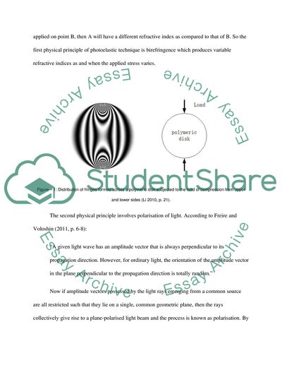
StudentShare
Contact Us
Sign In / Sign Up for FREE
Search
Go to advanced search...
Free

Stress Measurement and Photoelasticity - Assignment Example

Cite this document
Summary
Photoelasticity can be defined as a method of determining the distribution of stress in a given material. When mathematical methods become excessively complex for the purpose of stress determination, a photoelastic technique is preferred over other available techniques…
Download full paper File format: .doc, available for editing
GRAB THE BEST PAPER91.9% of users find it useful
Stress Measurement and Photoelasticity
Read Text Preview

Extract of sample "Stress Measurement and Photoelasticity"

Stress Measurement Photoelasticity 1. Photoelastic technique: General description Photoelasticity can be defined as a method of determining the distribution of stress in a given material. When mathematical methods become excessively complex for the purpose of stress determination, photoelastic technique is preferred over other available techniques (Li 2010). Therefore, it can be stated that the main philosophy behind photoelasticity is an urge for simplification of complicated technological processes. The main advantage of using photoelasticity is that it can give a fairly precise and intricate picture of distribution of stress in a given material. It can show stress variations around even the most abrupt structural discontinuities present in a substance. For example, Noselli, Del Corso, and Bigoni (2010) have stated that photoelasticity has been helpful in finding out stress intensities near a stiffener yielding results useful for studying fractures. 2. Physical principle behind the technique When a light ray is passed through certain transparent materials (e.g. epoxy), it encounters two refractive indices. For an illustration of how photoelastic polymeric materials help in visualising stress, refer to Figure – 1. Materials capable of producing double refraction in this way are called birefringent materials and the property is called birefringence (Phillips 1998). Birefringent materials are better technically termed as photoelastic materials. When such a material is subjected to stress, its refractive index changes proportionally with the stress applied (Li 2010). So, in a photoelastic material, if more stress is applied on point A and less stress is applied on point B, then A will have a different refractive index as compared to that of B. So the first physical principle of photoelastic technique is birefringence which produces variable refractive indices as and when the applied stress varies. Figure – 1: Distribution of fringes formed across a polymeric disk subjected to the load of compression from upper and lower sides (Li 2010, p. 21). The second physical principle involves polarisation of light. According to Freire and Voloshin (2011, p. 6-8): “A given light wave has an amplitude vector that is always perpendicular to its propagation direction. However, for ordinary light, the orientation of the amplitude vector in the plane perpendicular to the propagation direction is totally random.” Now if amplitude vectors possessed by the light rays emerging from a common source are all restricted such that they lie on a single, common geometric plane, then the rays collectively give rise to a plane-polarised light beam and the process is known as polarisation. By combining different plane-polarised light beams, elliptical and circular polarisations can also be created (Freire and Voloshin 2011). This physical principle is utilised in building a polariscope which is an optical instrument capable of analysing patterns of light rays emanating from a birefringent material. To analyse complex and irregular structures, generally a circular polariscope (see Figures 2a and 2b) is deployed that can analyse even the most complicated patterns of a circular polarised light beam emerging form the photoelastic testing material (Li 2010). In this way, physical principles of birefringence and polarisation of light are the two main conceptual pillars of photoelastic technique. Figure – 2a: Working of a plane polariscope (Kanth 1997). Figure – 2b: Working of a circular polariscope (Kanth 1997). 3. Procedure of using the technique The procedure for using the technique in practical measurement of stress involves a sophisticated but simple instrumentation with particular emphasis on the polariscope. First, a light ray is passed through the birefringent material (e.g. epoxy). Birefringence resolves amplitude vectors of the ray into two components. These components emanate into the two main stress directions. Now each component will go through a different refractive index. Consequently, each component then suffers phase retardation. A measurement of relative phase retardation involving the two differently refracted components can now be derived with the help of Stress-Optic Law (Freire and Voloshin 2011). If D is the relative phase retardation induced, then it is given by: D = (2πKT/λ) (f1 – f2) Where K = Stress-optic coefficient of the photoelastic material used T = Thickness of the photoelastic material λ = Wavelength of the light used f1 = 1st major stress factor f2 = 2nd major stress factor Furthermore, this induced relative phase retardation polarises the resultant light beam that emerges after the double refraction through the given photoelastic material (Freire and Voloshin 2011). Now a polariscope is deployed to analyse the fringe pattern of the refracted light. The fringe order N is given by: N = D/2π 4. Examples of industrial and technical applications In engineering, particularly where mechanical structures or buildings are involved, photoelasticity has diverse applications. A major industrial application area for photoelastic technique has been suggested by Noselli, Del Corso, and Bigoni (2010). In fracture studies, an understanding of the role and fatigue tolerating potential of stiffeners can be immensely refined with the help of photoelastic technique. Stiffeners help in forming rigid line inclusions in an elastic medium. For example, bend stiffeners can be utilised to hold up flexible objects like pipes, umbilical devices, cables and ducts when they are connected to stiff structures or some kind of afloat production system in which there is generally a necessity of controlling the lowest amount of permissible bend radius of the flexible object, say a pipe. (Balmoral Offshore Engineering 2014) Another example of industrial application is high speed fracture studies. In order to understand fatigue and fracture in rapidly moving machines, technologists need a tool to visualise the strain patters distributed across such materials, especially over the bimaterial surfaces. Photoelastic technique is becoming increasingly viable in this category of fracture studies. (Shukla 2012) Analysis of irregular surfaces is also possible by the aid of photoelastic technique with little compromise. Objects practically tested for stress have irregular surfaces in the real world scenario. However, if photoelastic coating on such a surface is developed sufficiently carefully, then stress patterns emanating through the structural irregularities of the given object can be diagnosed. “A photoelastic coating can be moulded to the surface contour of a complicated part and bonded to it. Light is reflected at the coating–component interface and therefore propagates twice through the coating thickness h, giving an effective path length of 2hin the coating. The component is now the primary load carrying member, not the photoelastic material. The in-plane coating strains are assumed to be equal to the in-plane surface strains in the component, and the analysis of the photoelastic patterns is based on the principal strain difference, which is related to the principal stress difference in the component through the elastic constants of the component material.” (Philips 1998, p. 6-62) Further in the context of analysing irregular surfaces, scientists at the University of Zurich (2014) have used photoelastic stress measurement technique to understand and analyse mechanical stimulation of the wings of a drosophila through the different developmental stages and phases of movement. Movements of the wings of this insect would not only help in understanding the bio-mechanical movements (and related stress patterns in a soft tissue system) but also can assist in developing aviation and aerodynamics related applications for industrial use. Strain Gauge 1. Strain gauge technique: General description Strain gauge technique is an instrumentation technique that helps in measuring the strain in a given object. There are three major kinds of strain gauge. These are (a) wire-based strain gauge, (b) foil gauge, and (c) semi-conductor gauge, which can be regarded as a complex and improvised case of foil gauge where semiconductor resistance element is used instead of using electric resistance alloys (see Figure – 3). Generally, the strain gauge has a sensitive metallic foil mounted on an insulated supple backing. The gauge has to be attached to the substance with the help of some adhesive. When the substance under examination is deformed, the foil is also deformed. Consequentially the electric resistance of the foil also changes variably at various points creating. The resistance changes are related with the strain measurable with the help of a Wheatstone bridge. In sum, “the bonded resistance strain gauge has been the most powerful single tool in the field of experimental stress analysis” (Starr 1992, p. 1). In the precise context of stress measurement, strain gauge can be used to measure the strain in a substance; whereas stress is equal to the magnitude of stress multiplied by the Young’s Modulus for that substance (College Physics 2013, chapter 5). Figure – 3: Three major kinds of strain gauge devices (Huang 2008). 2. Physical principle behind the technique Practically, strain gauging methods utilised by Origen (2014) employ electrical resistance strain gauges that are bonded to or pasted on the surface of the structure to be tested. “These thin foil gauges, essentially a length of wire formed into a grid, extend with the component as it strains to accommodate load which causes slight change in resistance of the length of wire” (Origen 2014). For a general representation of electro-mechanical strain gauge measurement instrumentation, refer to Figure – 4. Figure – 4: Instrument set for a mechanical strain gauge employing electric resistance material (Mastrad Quality and Test Systems 2014a). The physical principle on which the technology is based depends on the concepts around electrical conductance. Electrical resistance of a conductor depends on its structural geometry. Suppose a conductor is elongated within its elastic range of stretching. As the structural cross sectional area of the conductor becomes narrower, its electric resistance becomes larger. Likewise, if the conductor is shortened and broadened, its electric resistance is decreased. (College Physics 2013) 3. Procedure of using the technique The procedure for using the technique in practical measurement of stress depends on the electrical conductance patterns of the material of the gauge that is being used for measurement purpose (College Physics 2013). In this technique, a long and narrow strip of conducting material (e.g. a thin metallic foil) is arranged. The strip is pasted on the surface of the surface of the substance to be examined. Next, by passing current electricity and comparing the different magnitudes of resistances observed at different points, magnitude of strain is determined. Gauge factor or GF of the instrument that is being used helps the engineer in accomplishing this task. GF is given by: GF = (δR/Rg)/Є Where δR = Alteration in electric resistance caused by strain Rg = Un-deformed gauge electric resistance Є = Strain In the next step, stress is obtained by multiplying Є with the material’s Young modulus or Y. 4. Examples of industrial and technical applications Firstly, strain gauge technique has been used to diagnose crack widening rates and study related fracture development in buildings and constructions. For example, “mechanical strain gauge” (Huang 2008, p. 28) devices have been deployed in the famous Hudson-Athens Lighthouse to diagnose the patterns of crack widening so that development of serious fractures in the walls of the building can be prevented. Secondly, demountable mechanical strain gauges are also used for studying the stress patterns across a building or structure constructed with cement and concrete. However, these devices can be used to study steel structures as well. A typical industry standard demountable strain gauge has a principal digital dial which is attached with an Invar bar. An immovable conical point is positioned at one of the ends of the Invar bar, while a movable conical point is positioned on a “knife edge pivot” (Mastrad Quality and Test Systems 2014a) at the opposite side. The principal dial gauge measures the pivoting movements of the movable conical point. Special software programmes can be deployed to carry out necessary calculations and derive precise readings. Last but not least, strain gauges can be further modified to develop strain cylinders capable of evaluating performance of “compression load frames” (Mastrad Quality and Test Systems 2014b) which are utilised for examining concrete cubes and mortar cubes of cement. “The equipment comprises a steel strain cylinder of appropriate capacity fitted with four balanced strain gauge bridges. Each bridge is central at one of the ends of a pair of orthogonal diameters and is designed to be monitored by a separate panel meter.” (Mastrad Quality and Test Systems 2014b) Summary Principles of stress measurement using the photoelastic technique The physical principle on which the technology is based The procedure for using the technique in practical measurement of stress 3 examples of a typical industrial application of the technique The technique depends on the property of birefringence of certain materials like epoxy and it is aimed at developing relatively simpler stress diagnosis patterns in analysing most complex and irregular objects. 1. Birefringence 2. Polarisation of light A birefringent material is attached uniformly over the object to be tested. Next, light is refracted through the birefringent material and its fringe patterns are studied with the help of polarisation 1. Stress analysis and measurement in stiffeners 2. Fracture study in moving objects such as pistons, bearings, etc. 3. Study of irregular surfaces. Principles of stress measurement using strain gauges The physical principle on which the technology is based The procedure for using the technique in practical measurement of stress 3 examples of a typical industrial application of the technique   It is a simple tool to find out residual stresses in an object by diagnosing the existing strain patterns across the specimen object’s body. Electric conductance of a metallic material changes when strain is applied to it Generally, suitable metallic alloys are used in the form of a fine foil that is attached on the surface of the object to be tested. With the help of a Wheatstone Bridge device, generation of differences in electric resistance are measured across different points of the foil. 1. Detection of cracks and their widening rates in buildings. 2. Developing measurement tools to examine both concrete and steel structures. 3. Examination of compression frame loads. List of References Balmoral Offshore Engineering, 2014. Bend Stiffeners. Available: http://www.balmoral-group.com/balmoral-offshore-engineering/2-surf-bend-stiffeners.php. Last accessed on 25th January 2014 College Physics, 2013. Houston: OpenStax College, Rice University Freire, J.L.F. and Voloshin, A., 2011. Chapter 3, Experimental Mechanics, Paris: Encyclopaedia of Life Supporting Systems and UNESCO Huang, H., 2008. ST3: Strain Measurements (Chapter 10). University of Queensland: Electronic Instrument Lab. Available: http://www.mech.uq.edu.au/courses/metr3100/ST3_Strain_meas.pdf. Last accessed on 25th January 2014 Kanth, P.S., 1997. Photoelasticity Basics, Research in Automated Photoelasticity, Toronto: University of Toronto. Available: http://www.mie.utoronto.ca/labs/emdl/people/kanth/photo2.htm. Last accessed on 25th January 2014 Li, F., 2010. Study of Stress Measurement Using Polariscope, Thesis for Doctor of Philosophy in Mechanical Engineering, Georgia Institute of Technology: The Academic Faculty Mastrad Quality and Test Systems, 2014a. DEMEC Mechanical Strain Gauge. Available: http://www.mastrad.com/demecsg.htm. Last accessed on 26th January 2014 Mastrad Quality and Test Systems, 2014b. Compression Frame Stability Tester. Available: http://www.mastrad.com/footemtr.htm. Last accessed on 25th January 2014 Noselli, G., Del Corso, F., and Bigoni, D., 2010. Localized stress percolation through dry masonry walls: Part I – Experiments, European Journal of Mechanics and Solids, 29, pp. 291-298. Origen, 2014. Stress Measurement: The What, Where, and How. Available: http://www.origen.co.za/stressMeasurement.html. Last accessed on 25th January 2014 Philips, J.W., 1998. Photoelasticity. In: Experimental Stress Analysis, Sao Paulo: Instituto de Fisicia de Sao Carlos, pp. 6–1 - 6–62 Shukla, A., 2012. High-speed fracture studies on bimaterial interfaces using photoelasticity- A review, Journal of Strain Analysis for Engineering Design, 36, pp.119-142 Starr, J.E., 1992. Basic strain gage characteristics. In: R.L. Hannah and S.E. Reed (Eds.) Strain Gage Users’ Handbook, Springer: Heidelberg and London. University of Zurich, 2014. Studying the influence of mechanical forces on development, Measuring the Local Stresses in Wing Imaginal Discs, University of Zurich: Physics Institute. Available: http://www.physik.uzh.ch/groups/aegerter/research/Forces.html#. Last accessed on 25th January 2014 Read More
Cite this document
  • APA
  • MLA
  • CHICAGO
(Stress Measurement and Photoelasticity Assignment, n.d.)
Stress Measurement and Photoelasticity Assignment. Retrieved from https://studentshare.org/engineering-and-construction/1806345-stress-mesurement
(Stress Measurement and Photoelasticity Assignment)
Stress Measurement and Photoelasticity Assignment. https://studentshare.org/engineering-and-construction/1806345-stress-mesurement.
“Stress Measurement and Photoelasticity Assignment”, n.d. https://studentshare.org/engineering-and-construction/1806345-stress-mesurement.
  • Cited: 0 times

CHECK THESE SAMPLES OF Stress Measurement and Photoelasticity

Measurements And Methods

Research involves the collection and analysis of data to come up with conclusions regarding particular subject matters.... Various methods are utilized both in the collection as well as in the analysis of data.... hellip; Research involves the collection and analysis of data to come up with conclusions regarding particular subject matters....
3 Pages (750 words) Essay

The Concept of Stress

The concept of stress has received considerable theoretical and empirical attention in recent years because of a large number of people suffered from psychological and emotional disorders.... Major problems have to do not only with definitions of stress but also with proposed relationships between psychological stress and somatic illness.... hellip; stress is dangerous because it has a great impact on a psychological state of a person and its health....
2 Pages (500 words) Essay

Heat stress procedure

Since a man cannot do without a shelter, measures have… One of these is the heat stress procedure. Heat stress procedure highlights the health and safety principles and guidelines for applying a sufficient program in order to control heat in workshops, industries and The program's main objective is to reduce work related illnesses as a result of heat stress for it reduces work rate in all the above mentioned areas.... Besides, it serves to control heat related risks, outline causes, symptoms and treatment of heat stress....
5 Pages (1250 words) Essay

Stress Definition

stress is a result of physical and emotional nervousness and anxiety, which a person suffers due to pressures from people living in his surrounding or events happening… All of us undergo stress in our everyday lives.... For stress Nordqvist (2009, para defines stress as “anything that poses a challenge or a threat to our well-being”.... stress is a result of physical andemotional nervousness and anxiety, which a person suffers due to pressures from people living in his surrounding or events happening in his life....
1 Pages (250 words) Essay

Measurement Class-Assessment Project

In the paper “measurement Class-Assessment Project” the author analyzes the detection of a lie.... measurement Class-Assessment ProjectThe test construct I chose involves the detection of a lie.... The test and measurement results of this lie detector is quite controversial, as there are creations of mistakes....
1 Pages (250 words) Research Paper

Measurement Scales

The ratio scale is the most precise measurement and can be used for items such as the weight scale.... Ordinal scales are more precise and can be measurement Scales February 6 Nominal- A categorical variable that is used for mutual, exclusive, though not ordered categories (What is the difference…2013).... Interval scales are used for items such as F temperature where the measurement where the measurement if ordered from high to low....
1 Pages (250 words) Assignment

Measurement of intellectual capital

Its measurement measurement OF INTELLECTUAL CAPITAL This paper is concerned with the d regarding an interview held with john, an accounting lecturer who has full knowledge in management accounting.... Its measurement is difficult due to lack of standards.... There are measurement difficulties due to lack of measurement standards in these focuses.... The relationship of the financial gap between the business assets and the value of the business is difficult to understand because its measurement lacks standard....
1 Pages (250 words) Essay

Scales of Measurement for Human Intelligence

 This assignment "Scales of measurement for Human Intelligence" discusses An interesting phenomenon to study in psychology is to assess human intelligence.... easurement of IQ in this study will use the interval scale of measurement.... measurement of scale is appropriate because the IQ test satisfies the identity, magnitude and equal intervals properties of scale measurements....
1 Pages (250 words) Assignment
sponsored ads
We use cookies to create the best experience for you. Keep on browsing if you are OK with that, or find out how to manage cookies.
Contact Us