StudentShare
Contact Us
Sign In / Sign Up for FREE
Search
Go to advanced search...
Free

Fluid Mechanics: The Continuity Equation - Lab Report Example

Cite this document
Summary
This lab report "Fluid Mechanics: The Continuity Equation" proves both the Continuity equation and Bernoulli’s equation. As the difference in the flow occurs due to the difference in the diameter of the tubes the velocity of the water is found to be more in the pipe with a lesser diameter…
Download full paper File format: .doc, available for editing
GRAB THE BEST PAPER91.4% of users find it useful
Fluid Mechanics: The Continuity Equation
Read Text Preview

Extract of sample "Fluid Mechanics: The Continuity Equation"

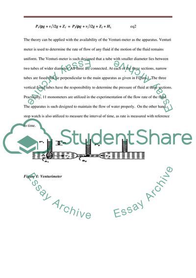
Laboratory Report: Fluid Mechanics The rate of flow of water will be determined by analyzing its flow through pre determined cross section. The designed tube to determine the rate of flow of water is a converging and a diverging tube. The rate of flow alters are different sections of the tube. The diameter will help to determine the flow of water. Introduction The major goal that is to be determined through the experiment is to analyse the flow manner of water through an enclosed pipe. For the evaluation of the flow, the Bernoulli’s equation and Continuity equation will be utilised. The Continuity Equation depicts the mathematical form of the “law of conservation of mass”. It is a fact that an enclosed body like a pipe make the flow of water or any other fluid to have no flow velocity components in regular direction, as, the enclosed body makes the flow to be also the tangential direction (Sahu and Sahu, 2009). Utilizing the law of conservation of mass, the above phenomenon can be mathematically interpreted as: Q = A1 × v1 = A2 × v2 eq1 On the other hand, the Bernoulli’s equation well depicts the change in the flow of fluid at two different points (Sahu and Sahu, 2009). Regarding the above situation, the Bernoulli’s equation can be written as: P1/ρg + v12/2g + Z1 = P2/ρg + v22/2g + Z2 + HL eq2 The theory can be applied with the availability of the Venturi-meter as the apparatus. Venturi meter is used to determine the rate of flow of any fluid if the motion of the fluid remains uniform. The Venturi-meter is such designed that a tube with smaller diameter lies between two tubes of wider diameter. All three are connected. At each of the three sections, narrow tubes are fused that lie perpendicular to the main apparatus as given in Figure 1. The three vertical fused tubes have the responsibility to determine the pressure of fluid at three sections. Practically, 11 monometers are utilized in the experimentation of the flow rate of the fluid. The apparatus is such designed to maintain the flow of water properly. On the other hand, stop watch is also utilized to measure the interval of time, as rate is measured with reference to time. Figure 1: Venturimeter Results S No. Position of the tube, x Diameter d (mm) Area A (10-6 m2) Velocity v (= Q/A) (m/s) Velocity Head Evh(= v2/2g) (m) Tube Height h (mm) Static Head Esh (= P/ρg) (m) Etotal = Evh + Esh (m) 1. 1 25.4 506.7 0.26 0.0035 245 0.245 0.2485 2. 2 22.8 408.3 0.32 0.0052 245 0.245 0.2502 3. 3 18.5 268.8 0.49 0.0123 240 0.24 0.2523 4. 4 15.8 196.1 0.68 0.0236 230 0.23 0.2536 5. 5 16.4 211.2 0.63 0.0203 230 0.23 0.2503 6. 6 17.8 248.8 0.53 0.0143 235 0.235 0.2493 7. 7 19.2 289.5 0.46 0.0108 237 0.237 0.2478 8. 8 20.6 333.3 0.40 0.0082 242 0.242 0.2502 9. 9 21.8 373.3 0.36 0.0066 244 0.244 0.2506 10. 10 23.1 419.1 0.32 0.0052 245 0.245 0.2502 11. 11 25.4 506.7 0.26 0.0035 245 0.245 0.2485 Table 1: 10 L inflow 10 L inflow Time 75.55 sec Flow rate = = 10/75.55 = 0.1324 litres/sec = 0.1324 X 10⁻³ m3/sec Volumetric Flow Rate, Q = 132.4 X 10⁻⁶ m3/s Figure 1.1: 10 litres Velocity Head for Inflow 10 litres Static Head for Inflow Velocity Head (in blue) Static Head (in red) in Total Energy for 10 litres Inflow 20 litres Inflow Time 59.08 sec flow rate = 20/59.08 = 0.3385 litres/sec = 0.3385 X 10⁻³ m3/sec Volumetric Flow Rate, Q = 338.5 X 10⁻⁶ m3/s S. No. Position of the tube, x Diameter d (mm) Area A (10-6 m2) Velocity v (= Q/A) (m/s) Velocity Head Evh(= v2/2g) (m) Tube Height h (mm) Static Head Esh (= P/ρg) (m) Etotal = Evh + Esh (m) 1. 1 25.4 506.7 0.67 0.0229 243 0.243 0.2659 2. 2 22.8 408.3 0.83 0.0351 237 0.237 0.2721 3. 3 18.5 268.8 1.26 0.081 200 0.2 0.281 4. 4 15.8 196.1 1.73 0.1527 130 0.13 0.2827 5. 5 16.4 211.2 1.6 0.1306 140 0.14 0.2706 6. 6 17.8 248.8 1.36 0.0944 173 0.173 0.2674 7. 7 19.2 289.5 1.17 0.0698 192 0.192 0.2618 8. 8 20.6 333.3 1.02 0.0531 205 0.205 0.2581 9. 9 21.8 373.3 0.91 0.0423 215 0.215 0.2573 10. 10 23.1 419.1 0.81 0.0335 221 0.221 0.2545 11. 11 25.4 506.7 0.67 0.0229 230 0.23 0.2529 Table 2 Total Energy at the inflow valve 0.2659 Outflow valve was 0.2529 Head Lost due to fluid resistance: (HL)20lit = 0.2659 – 0.2529 = 0.013m Velocity Head Inflow = 20 litres Static Head Inflow = 20 litres Velocity Head blue Static Head red in Total Energy for 20l Inflow 25l Inflow Time 53.77 sec Flow rate = 25/53.77 = 0.4649 litres/sec = 0.4649 X 10⁻³ m3/sec Volumetric Flow Rate, Q = 464.9 X 10⁻⁶ m3/s S. No. Position of the tube, x Diameter d (mm) Area A (10-6 m2) Velocity v (= Q/A) (m/s) Velocity Head Evh(= v2/2g) (m) Tube Height h (mm) Static Head Esh (= P/ρg) (m) Etotal = Evh + Esh (m) 1. 1 25.4 506.7 0.67 0.0229 243 0.243 0.2659 2. 2 22.8 408.3 0.83 0.0351 237 0.237 0.2721 3. 3 18.5 268.8 1.26 0.081 200 0.2 0.281 4. 4 15.8 196.1 1.73 0.1527 130 0.13 0.2827 5. 5 16.4 211.2 1.6 0.1306 140 0.14 0.2706 6. 6 17.8 248.8 1.36 0.0944 173 0.173 0.2674 7. 7 19.2 289.5 1.17 0.0698 192 0.192 0.2618 8. 8 20.6 333.3 1.02 0.0531 205 0.205 0.2581 9. 9 21.8 373.3 0.91 0.0423 215 0.215 0.2573 10. 10 23.1 419.1 0.81 0.0335 221 0.221 0.2545 11. 11 25.4 506.7 0.67 0.0229 230 0.23 0.2529 Table 3 There appears to be discrepancy in the total energy. This is because the inflow valve was 0.2793 and the outflow was 0.2402 Fluid resistance impacted the Head Loss: (HL)25lit = 0.2793 – 0.2402 = 0.0391m. Velocity Head Inflow = 25 L Static Head Inflow = 25 L Velocity Head blue Static Head red Total Energy for Inflow 25 L Conclusion The experiment proves both the Continuity equation and the Bernoulli’s equation. As the different in the flow occurs due to the difference in the diameter of the tubes, the velocity of the water is found to be more in the pipe with lesser diameter that proves the Continuity equation to be correct and valid. On the other hand, the pressure in the three sections are different that makes the venturi-meter to fluctuate, which verifies the Bernoulli’s equation. It is concluded from the experiment that head lost is caused by the resistance in the flow of the fluid. The increase in the velocity of the fluid is due to the fact the venturi-meter tries to maintain the rate of flow. In this way, it can be said that the energy that makes a fluid flow become constant. I is clearly determined that the flow rate of fluid changes from 132.4 X 10⁻⁶ m3/s, 10 litre volume to 464.9 X 10⁻⁶ m3/s, 25 litre volume. On the other hand, as the rate of flow increase the viscous resistance also increases which, consequently amplifies the Head lost from 0 at the volume of 10L to about 0.013m at the volume of 20L and 0.0391m at the volume of 25L. From the experiment, it can be concluded that the static head and velocity head deform in decreased cross sectional regions of the fluid flowing. That changes the behaviour of the flow to turbulent from laminar. References Handbook of Piping Design By Sahu, Sahu G.K. (2009) Read More
Tags
Cite this document
  • APA
  • MLA
  • CHICAGO
(Fluid Mechanics: The Continuity Equation Lab Report Example | Topics and Well Written Essays - 1250 words, n.d.)
Fluid Mechanics: The Continuity Equation Lab Report Example | Topics and Well Written Essays - 1250 words. https://studentshare.org/physics/1791243-fluid
(Fluid Mechanics: The Continuity Equation Lab Report Example | Topics and Well Written Essays - 1250 Words)
Fluid Mechanics: The Continuity Equation Lab Report Example | Topics and Well Written Essays - 1250 Words. https://studentshare.org/physics/1791243-fluid.
“Fluid Mechanics: The Continuity Equation Lab Report Example | Topics and Well Written Essays - 1250 Words”. https://studentshare.org/physics/1791243-fluid.
  • Cited: 0 times

CHECK THESE SAMPLES OF Fluid Mechanics: The Continuity Equation

A Syndrome of High Blood Pressure

(“Aldosteronism, APMA)When physicians diagnose patients with low sodium levels and high blood pressure they may have them undergo additional testing to find out if they have Aldosteronism because of aldosterone's normal function of increasing sodium and fluid in the bloodstream and to increase potassium excretion in the kidney....
7 Pages (1750 words) Research Paper

Velocity and Flow Rate Measuring Instruments used in Pipes

Some relevant principles of fluid mechanics that are underlying principles of various flow velocity and flow rate measuring types of equipment are – “Pascal's Law”, “Equation of Continuity” and Bernoulli's Equation”.... his is essentially a statement of the law of conservation of matter as applied in fluid mechanics.... his equation is essentially a statement of the law of conservation of energy as applied in fluid mechanics....
6 Pages (1500 words) Essay

THERMODYNAMICS AND FLUID MECHANICS

Generally, any adjustments that such piping system may undergo would occur such that the change or effect obeys Bernoulli's principle via Bernoulli's equation.... As illustrated in the diagram, the HGL (imaginary segments) and the EGL (solid segments) each consists of… It may be observed that the HGL almost assumes the same shape and slope of EGL just as the left-hand side of the Bernoulli's equation merely The difference between the HGL and the EGL signifies ‘head losses' that correspond to change in the state of pressure, velocity, and fluid level that altogether appear in the Bernoulli's...
6 Pages (1500 words) Assignment

Fluid mechanical

undamentals of fluid mechanics (6th ed.... The fluid motion in this case is powered by gravitational force. You must have a pipe in a U shape which allows the Magic Fountain By Magic Fountain 0 Upward fluid movement The first person(s) to do an experiment on upward fluid movement were two Egyptian brothers, the Banu Musa brothers who invented a double-concentric siphon.... The fluid motion in this case is powered by gravitational force....
2 Pages (500 words) Coursework

Thermodynamics and fluids mechanics

U in the theory equation represents initial velocity just like the v in the experimental equation.... This can be seen clearly from the graph where the three graphs are of straight lines coming from the origin.... As the volume of the water collected reduces, the jet momentum… For example, when the volume was 15 liters, the jet momentum was 4....
4 Pages (1000 words) Lab Report

Application of Engineering Principles

Or, if more than two viscosities are known, the data can be correlated with the above equation by using some type of curve fitting scheme.... This equation is often referred to as Andrade's equation.... he figure shows in more detail how the viscosity varies from fluid to fluid and how for a given fluid it varies with temperature, whereas for gases an increase in temperature causes an increase in viscosity....
8 Pages (2000 words) Assignment

Experimenting with Fluid Mechanics

In this case only the initial piezometer tube A and the throat piezometer tube D are requiredBernoulli's equation may be arranged as From continuity equation =height of water in vertical tube at A(m)= height of water in vertical tube at D(m)Thus with the knowledge of g, AD, AA and taking measurement of the amount of fluid flow is determined However, due to losses when the equation is in this form accurate result is not obtained and this makes it necessary to have a constant (c) to determine calibrationResults With the use of relevant equations in excel the following result was obtained Table 1TRIALTIME(s)Weight(N)Height of water(cm)ADc140....
5 Pages (1250 words) Assignment
sponsored ads
We use cookies to create the best experience for you. Keep on browsing if you are OK with that, or find out how to manage cookies.
Contact Us