StudentShare
Contact Us
Sign In / Sign Up for FREE
Search
Go to advanced search...
Free

Overload protection systems and mechanics of machines - Essay Example

Cite this document
Summary
Machines and electrical equipment while useful in the performance of work can pose a lot of danger to people and equipment in case they experience faults or are subjected to overloads. Overload protection systems play a great role in protecting people and equipment from harm that may result from such faults or overloads. …
Download full paper File format: .doc, available for editing
GRAB THE BEST PAPER94.1% of users find it useful
Overload protection systems and mechanics of machines
Read Text Preview

Extract of sample "Overload protection systems and mechanics of machines"

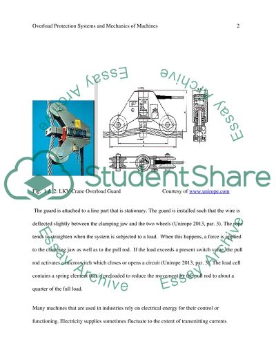
?Overload Protection Systems and Mechanics of Machines Overload Protection Systems and Their Applications Machines and electrical equipment while useful in the performance of work can pose a lot of danger to people and equipment in case they experience faults or are subjected to overloads. Overload protection systems play a great role in protecting people and equipment from harm that may result from such faults or overloads. Overload protection systems normally feature overload switches or relays that serve to cut off power supplies to certain elements of the system and, therefore, prevent the machine from working normally (Gurevich 2003, p. 57). There are different overload protection systems that exist, each with its specific function and application. In industries that involve the movement of heavy loads, overload protection systems are installed to ensure that the machine, equipment and people are protected against injustices or damages that may occur in case the machine is loaded beyond its capacity (Gurevich 2003, p. 183). Systems that protect against weight overload commonly exist on cranes and elevators. There are also machines that work in environments that feature a lot of heat. Some machines are installed with protection systems to prevent them from damage by extreme heat or cold. These systems are fitted with sensors that prevent them from functioning normally under adverse thermal conditions. One example of an overload protection system used in cranes is the LKV Crane Overload Guard. Figures 1 and 2 show the LKV Crane Overload Guard. Fig. 1 & 2: LKV Crane Overload Guard Courtesy of www.unirope.com The guard is attached to a line part that is stationary. The guard is installed such that the wire is deflected slightly between the clamping jaw and the two wheels (Unirope 2013, par. 3). The rope tends to straighten when the system is subjected to a load. When this happens, a force is applied to the clamping jaw as well as to the pull rod. If the load exceeds a present switch value, the pull rod activates a microswitch which closes or opens a circuit (Unirope 2013, par. 3). The load cell contains a spring element that is preloaded to reduce the movement by the pull rod to about a quarter of the full load. Many machines that are used in industries rely on electrical energy for their control or functioning. Electricity supplies sometimes fluctuate to the extent of transmitting currents beyond the ratings of machines or their components. To prevent electrical and electronic systems from damages that result from too much, too low or fluctuating currents or voltages, some machines are fitted with overload switches (Gurevich 2003, p. 124). Scientific Principles of Mechanics of Machines A machine is basically a tool or equipment that makes work easier and faster. Machines commonly use electrical, chemical, thermal, or mechanical energy to meet the objectives for which they are intended. Many machines that are used today are complex in nature and often times comprise one or more simple machines and computer systems. Simple machines include levers, pulleys, wheels and axels, inclined planes, screws, and wedges. Mechanical Advantage Machines are specifically designed to make work easier and faster. The level to which a machine makes work faster or easier is known as the mechanical advantage (MA). In Engineering and physics, mechanical advantage is defined as the number of times a machine multiplies the effort implied into it (ThinkQuest 2013, par. 1). In other words, it is the ratio of exerted working force produced by a machine to the effort applied, the units of force being measured in Newtons. In order to determine the mechanical advantage of a machine, one needs to divide the resistance force by the force of effort (ThinkQuest 2013, par. 1). In many cases, the resistance force is equal to the weight of the object. Mechanical Advantage of Pulley Systems A pulley is basically a machine that comprises a wheel that has a groove. A cable, belt or rope runs inside the groove to lift or lower loads and to make work easier. A pulley can be used alone or it can be connected to one or more other pulleys to form a pulley system. A pulley or system of pulleys can be used to change direction of rotation, torque or force, or to change speed. By using a pulley or pulley system to lift an object, the load becomes easier to lift since the pulleys reduce the amount of effort that is required for the lifting of the object. As the number of pulleys in a pulley system increases, the force that will be required to lift a load becomes less. In other words, if one needs to use the least energy to lift an object, they should use the maximum number of pulleys at their disposal. As the lifting becomes easier, the rope or belt that runs through the pulley travels a greater distance than the actual height from which the load is to be lifted to where it needs to be repositioned (iqa.evergreenps 2013). What this means is that as the extra distance of travel lowers the effort that one needs to apply to lift the load by giving mechanical advantage. The mechanical advantage of a pulley or pulley system can be calculated by dividing the weight of the object (or frictional force implied by the object) to be lifted by the pulley or pulley system by the force that is used to lift the load through the pulley system. Alternatively, the mechanical advantage of a pulley or pulley system can be determined by establishing the distance (F) between the fulcrum and the input point of contact of the force and the distance (L) between the fulcrum and the point at which the load is in contact with the lever (iqa.evergreenps 2013, par. 7). The mechanical advantage is the ratio F: L or the result of dividing F by L. It is quite easy to establish the mechanical advantage of a system of pulleys. The mechanical advantage is simply equal to the number of doubled up stretches of code that the pulley system has (ThinkQuest 2013, par. 2). For example, the mechanical advantage of a system containing two pulleys is two (one pulley is immovable). What this means is that the mechanical advantage of a system that has n pulleys is equal to twice the number of pulleys involved (2n). This can be summarised as follows: Mehanical Advantage = Load /Effort Mechanical advantage (M.A.) of a system of n pulleys = 2n Where n is the number of movable pulleys Velocity Ratio of Pulley Systems The velocity ratio (VL) of a machine is the ratio of distance moved by point of effort to that moved by the point of load (BBC 2013, par. 1). Velocity ratio of a machine is represented by the general formula: VL=Effort distance/Load distance Like other machines, the velocity ratio of a pulley or pulley system can be determined. Worth noting is that the velocity ratio for a system that has one pulley is equal to one since the distance moved by the load and effort is always equal. Two or more pulleys that have different diameters can form a pulley system. When two pulleys form a system, the velocity ratio of the system is equal to the ratio of the diameter of the pulley being driven to the diameter of the driver pulley (BBC 2013, par. 1). Alternatively, the velocity ratio is the result of dividing the input speed by the output speed. The velocity ratio of a system of two pulleys can also be determined by dividing the output torque by the input torque (BBC 2013, par. 1). These relationships can be summarised by the formulae that follow: Velocity ratio = diameter of the driven pulley ? diameter of the driver pulley Velocity ratio = output speed ? input speed Velocity ratio = output torque ? input torque (BBC 2013, par. 2-4). First Pulley System Worth noting is that pulley system configurations are associated with different velocity ratios. In a system of pulleys so arranged that the lowest pulley bears the load that is to be lifted and hangs on the rest of the pulleys by their axels as shown in figure 1, the velocity ratio is given by the formulae: Velocity Ratio = Distance covered by effort/Distance covered by load Velocity Ratio = 2n Fig. 2: Two pulleys with a load hanging on the lower pulley Courtesy of www.grandpapencil.net Second Pulleys System In a system of pulleys can be configured such that it has two or more blocks of pulleys; one of them fixed. On the fixed pulley block, there are pulleys that rotate freely about their individual axes. The pulleys in this block get support from one common axel which is fixed to a frame. The other blocks of pulleys may be configured similar to the first one, the only difference being that the entire structure is supported by a string that is intertwined. One end of the code goes over the uppermost pulley and bears the effort even as the load is supported by the lowest block as shown in figure 2. Fig. 2: Two blocks of pulleys Courtesy of http www.grandpapencil.net For such a system containing two blocks, the velocity ratio is represented by the formula VR = The distance moved by P The distance moved by W VR =nx/x Therefore, VR= n Where n is the number of pulleys in the system (Stonecypher, 2011, par. 3) Third System of Pulleys In a pulley system that features the topmost pulley fixed to a rigid frame and the load borne by each of the pulley individually as shown in figure 3, the velocity ratio is represented by the formulae that follow: VR = The distance moved by P The distance moved by W VR= 2n – 1 (Stonecypher, 2011, par. 3) Fig 3: Third pulley system configuration Courtesy of www.brighthubengineering.com The Relationship between the Mechanical Advantage, Velocity Ratio and Efficiency of a Machine The law of conservation of energy states that the energy input into a machine is always equal to the total amount of energy output by the system (Kurtus 2013, par 2). Although this is the case, not all the energy output by a machine is output as work. Rather, some of the energy is lost in different ways such as friction or heat. The efficiency of a machine relates to how effective the machine is in transforming input power or energy into movement of output force. In other words, the efficiency of a machine is the ratio of energy input in the machine to the valuable work output by the machine (Kurtus 2013, par 2). What this means is how useful a machine is is a factor of its efficiency. This relationship can be summarised in the formula: Efficiency = Wo/Wi Where Wo represents energy or Work output and Wi represemts energy or work input (Kurtus 2013, par 2). The efficiency of a mechanical system can also be measured by finding the ratio between measured performance and ideal performance (Gujral 2008, 379). Important to note is the fact that ideal performance is theoretical and does not exist in reality since there are no frictionless and absolutely rigid machines. Also worth noting is that the efficiency of a machine cannot be 100% in reality since some of the energy that is output is lost in the form or heat, wear and tear, and friction. The efficiency of a machine is a factor or its mechanical advantage and velocity ratio. The relationship between the efficiency of a machine, its mechanical advantage, and its velocity ratio can be represented by the formula: Efficiency = {Mechanical Advantage/Velocity Ratio} x 100 (Gujral 2008, 379) References BBC 2013, Design and Technology: Pulley Systems, viewed 7 November, 2013 Gujral I. 2008, Engineering Mechanics, Firewall Media, New York Gurevich V. 2003, Protection Devices and Systems for High-Voltage Applications, Taylor & Francis, London. iqa.evergreenps 2013, Mechanical Advantage of Simple Machines, viewed 7 November, 2013 Kurtus R. 2013, Efficiency of Machines, viewed 7 November, 2013 Stonecypher L. 2011, Calculation Methods for Pulley Systems, viewed 7 November, 2013 ThinkQuest 2013, What is Mehanical Advantage? , viewed 7 November, 2013 Unirope 2013, PIAB LKV Overload Guard, viewed 7 November, 2013 Read More
Tags
Cite this document
  • APA
  • MLA
  • CHICAGO
(“Overload protection systems and mechanics of machines Essay”, n.d.)
Overload protection systems and mechanics of machines Essay. Retrieved from https://studentshare.org/engineering-and-construction/1489701-overload-protection-systems-and-mechanics-of-machines
(Overload Protection Systems and Mechanics of Machines Essay)
Overload Protection Systems and Mechanics of Machines Essay. https://studentshare.org/engineering-and-construction/1489701-overload-protection-systems-and-mechanics-of-machines.
“Overload Protection Systems and Mechanics of Machines Essay”, n.d. https://studentshare.org/engineering-and-construction/1489701-overload-protection-systems-and-mechanics-of-machines.
  • Cited: 0 times

CHECK THESE SAMPLES OF Overload protection systems and mechanics of machines

OSHA Standards Requirements for Safety Management

If an exhaust system is used, the guard must form part of the exhaust system • All of the metal framework on electrically driven machines must be grounded, including the motor, motor casing, legs, and frame.... This accounted for 25% of all major accidents and one of last year's two deaths in the woodworking industry. • Enclose the upper half… Guard the lower half with a self adjusting, floating guard that rises and falls and automatically adjusts to the thickness of the stock. • Enclose the spindle with an adjustable guard or cage....
12 Pages (3000 words) Research Paper

Building Services system

The system should serve the general purposes of power in a house including running of two hose reel pumps requiring a total of 2.... kw and a chiller requiring 600A.... These will be the… The type of the power system will be a 3-phase system with a 2,400 V voltage.... The system is efficient and observes all the regulations of the relevant authorities including the engineering code of practice....
12 Pages (3000 words) Essay

Costing Systems in the Manufacturing Environment

Costing systems are essential in a manufacturing setup because it enables an organisation to establish its expenditure on production in relation to revenue generation.... Production innovation is essential in establishing cost effective production methods such as automation of the production line and use of digital systems to reduce the cost of power and labour (Frost, 2005)....
6 Pages (1500 words) Essay

Vessels Electrical Distribution System

In this scenario, we must be able to provide detailed attention on the complex distribution and control systems and a focus on the special operation and reliability.... The author of this term paper "Vessels Electrical Distribution System" focuses on the origin of a vessel that carries with it people, machines, equipment, and many other technology-related and tools for industrial, commercial and individual uses.... These are vessels that apply complicated operational systems as an extra precaution against accidents....
17 Pages (4250 words) Term Paper

Toyota Sewing System

Under the system, it has been regulated that the fewer num­bers of multi-functional operators perform their services on the machines which are usually prearranged in a “U-line.... The performance of TSS is fundamental on the principle of “pull-type production systems”, in which the job order is completed in descending order i.... The three layers of manufacturing systems generally adapted to the accumulation of manufacturing garments are: Each sewing system necessitates an adequate philosophy of the organization, materials handling methodology, floor layout and staff training....
8 Pages (2000 words) Case Study

Bearing as the Main Part in the Majority of Machines

This paper “Bearing as the Main Part in the Majority of machines” addresses the classification of rolling bearings, stages of bearing defect, time and frequency domain, interpretation of vibration data, types of vibration transducers (displacement probes, velocity transducers, accelerometers) etc.... hellip; Most bearings are used to support rotating shafts in machines and generate energy losses by wear and friction.... Bearings that are properly selected, correctly lubricated, and protected from abuse will usually outlast the machines in which they are installed The optimum duration bearing life is achieved when worsening due solely to rolling fatigue finally results in favorable operation....
16 Pages (4000 words) Coursework

Overload Protection Systems

This work called "overload protection systems" describes mechanical and hydraulic overload protection systems.... The most common overload protection systems are mechanical and hydraulic overload protection systems.... Mechanical overload protection systems are used in mechanical presses; the working principle is based on a delicate sheer plate that requires approximately 130% capacity to be broken.... Hydraulic overload protection systems are more common because the force of the press can be restricted by controlling the hydraulic pressure, and the press can be restarted after an incidence of overload without having to change the plates (Altan & Tekkaya, 2012)....
6 Pages (1500 words) Essay

The Design of Basic Mechanical Systems

The paper "The Design of Basic Mechanical Systems" highlights that poor operator judgment is among the common causes of accidents encountered when using drilling machines.... hellip; Single spindle drilling machines are used in the mechanical industry in order to maximize the productivity of machining systems when drilling holes in a workpiece.... Drilling machines are used for cutting circular holes, including dug-in holes, in items using a rotating component known as a bit or drill....
5 Pages (1250 words) Essay
sponsored ads
We use cookies to create the best experience for you. Keep on browsing if you are OK with that, or find out how to manage cookies.
Contact Us